EasyManua.ls Logo

Beckhoff TwinSAFE logic FB User Manual

Beckhoff TwinSAFE logic FB
217 pages
To Next Page IconTo Next Page
To Previous Page IconTo Previous Page
Page #215 background imageLoading...
Page #215 background image
Function blocks
Function blocks for TwinSAFE logic components 213
Table 3-193: State information
Value
Description
1
RUN
The FB XOR module assumes the RUN state if the input FbRun is TRUE.
The outputs assume the following values, depending on the active input pairs
(configuration: FB Input Active):
XorOutY = (Xor1InY XOR Xor2InY) AND FB Input Active(Y) with Y = {1,2 .. 8}
2
STOP
The FB XOR module assumes the STOP state if the input FbRun is FALSE.
The outputs assume the following values:
XorOutY = 0 with Y = {1,2 .. 8}
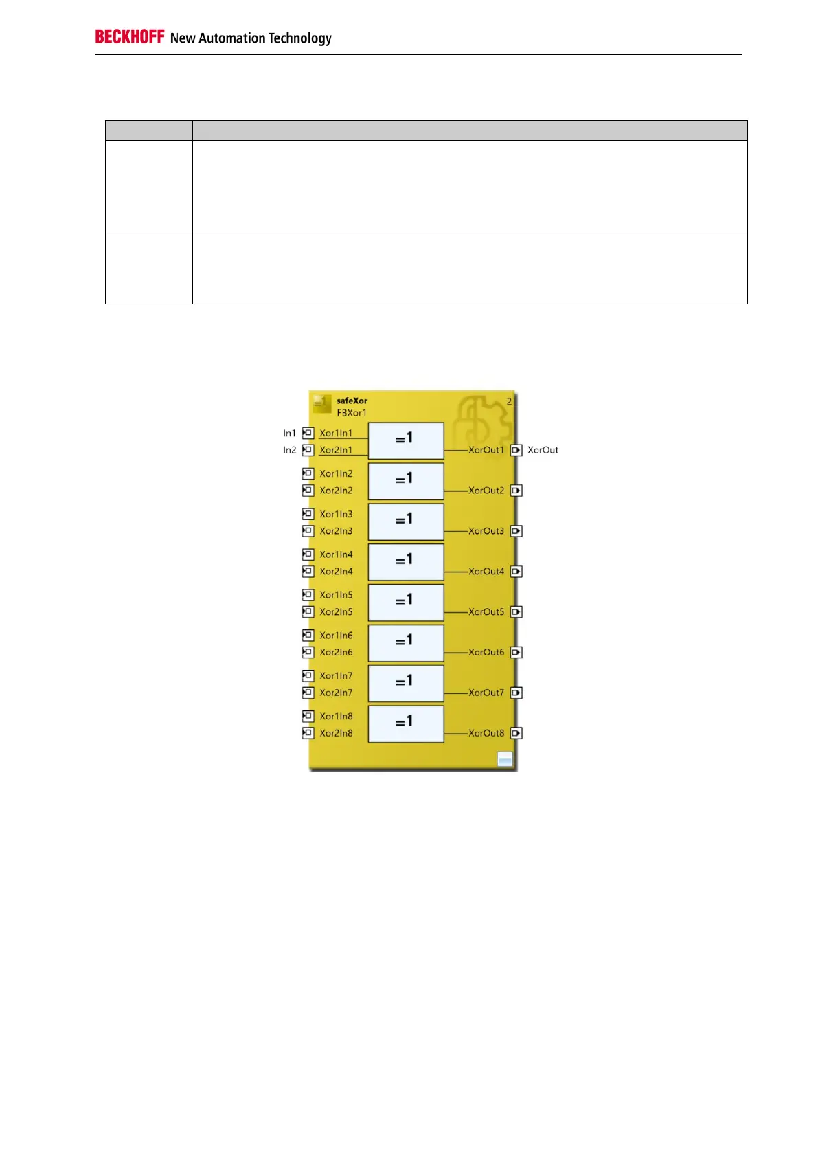
3.30.3 Configuration of the FB XOR in TwinCAT 3
Figure 3-137: FB XOR configuration
A mouse click next to the respective FB Port can be used to create variables that can be linked to input or
output signals. The properties of the FB Port can be used for settings such as port activation.
The MapState and MapDiag entries define which diagnostic functions of the FB are mapped to the cyclic
process image.

Table of Contents

Question and Answer IconNeed help?

Do you have a question about the Beckhoff TwinSAFE logic FB and is the answer not in the manual?

Beckhoff TwinSAFE logic FB Specifications

General IconGeneral
BrandBeckhoff
ModelTwinSAFE logic FB
CategoryIndustrial Electrical
LanguageEnglish

Summary

1 Foreword

Notes on the Documentation

Information regarding the documentation's target audience, origin, currentness, and symbols used.

Safety Instructions

Guidance on safety instructions, delivery state, operator diligence, and explanation of notes.

2 System Description

TwinSAFE Logic Terminals and Connections

Details on TwinSAFE logic terminals, groups, connections, and configuration. Includes diagnosis overview.

System Diagnosis

Information on diagnosing TwinSAFE system components, including diagrams for TwinCAT 2 and TwinCAT 3.

3 Function Blocks

The Function Block AND

Functional description, signal details, diagnostic info, and TwinCAT configuration for the AND logic block.

The Function Block OR

Functional description, signal details, diagnostic info, and TwinCAT configuration for the OR logic block.

The Function Block OPMODE

Description of OPMODE function block for operation mode selection and restart behavior.

The Function Block ESTOP

Details on ESTOP function block: description, signals, configuration, restart behavior, and extensions.

The Function Block MUTING

Description of MUTING block, signals, configuration, examples, and extensions for EL/EJ6910.

The Function Block TON

Functional description, signal details, diagnostic info, and TwinCAT configuration for the TON delay timer.

The Function Block TOF

Functional description, signal details, diagnostic info, and TwinCAT configuration for the TOF delay timer.

The Function Block ADD

Description of ADD block for analog addition: signals, diagnostics, and TwinCAT configuration.

The Function Block SUB

Description of SUB block for analog subtraction: signals, diagnostics, and TwinCAT configuration.

The Function Block COMPARE

Description of COMPARE block for analog input comparison, including architectures, signals, and config.

The Function Block LIMIT

Description of LIMIT block for checking analog input values against Min/Max limits, including signals and config.

The Function Block COUNTER

Description of COUNTER block for up/down counting: signals, diagnostics, and TwinCAT configuration.

The Function Block CAMMONITOR

Description of CAMMONITOR block for electronic cam control: modes, inputs, outputs, parameters, and diagnostics.

4 Appendix

Beckhoff Support and Service

Information on contacting Beckhoff for technical support, system solutions, and after-sales service.

Beckhoff Headquarters Information

Contact details, phone, fax, email, and web address for Beckhoff Automation GmbH & Co. KG.

Related product manuals