Function blocks
40 Function blocks for TwinSAFE logic components
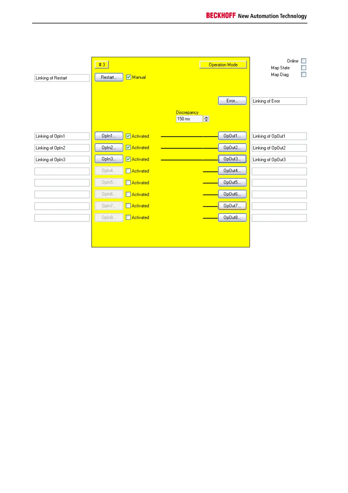
3.3.3 Configuration of the FB OPMODE in the TwinCAT System Manager
Figure 3-10: FB OPMODE configuration
The manual restart is activated using the "'Activated' " checkbox on the right near the 'Restart' button.
The inputs are activated via the 'Activated' check boxes to the right of the 'OpIn (x)' button.
The 'Restart' or 'OpIn(x)' buttons can only be selected, once the corresponding check box has been
selected.
The FB OPMODE input variables are linked using the 'Restart' and 'OrIn(x)' buttons.
The FB OPMODE output variables are linked using the 'Error' and 'OpOut(x)' buttons.
The 'MapState' and 'MapDiag' checkboxes are used to specify which FB diagnostic functions are mapped
to the cyclic process image.
The discrepancy time is configured using the 'Discrepancy' selection box.

 Loading...