System description
Function blocks for TwinSAFE logic components 11
2 System description
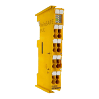
The TwinSAFE system consists of safe inputs (EL/KL1904), safe outputs (EL/KL2904) and logic modules
(KL6904/EL6900/EL6910/EJ6910). The TwinSAFE logic terminal (KL6904/EL6900/EL6910/EJ6910)
contains function blocks, which can be parameterized and connected to each other and form the safety-
related logic. Free programming is not possible. In addition to the non-safety-related logic configuration a
fieldbus configuration is required for mapping the TwinSAFE data packets. These functions are realized
via the TwinCAT System Manager or TwinCAT 3. The safety-relevant TwinSAFE Verifier or TwinCAT 3
handles loading and checking of the TwinSAFE project on the EL69x0/KL6904/EJ6910.
The TwinSAFE logic terminal can communicate, via the fieldbus-independent and certified TwinSAFE-
protocol with safe input and output terminals, and also via further logic terminals. The TwinSAFE protocol
is the Safety-over-EtherCAT (FSoE) protocol, as disclosed in the EtherCAT Technology Group
(www.ethercat.org).
2.1 TwinSAFE logic terminals EL69x0/KL6904/EJ6910
The configuration of a TwinSAFE logic terminal consists of function blocks and connections that are
consolidated into one or several TwinSAFE groups. TwinSAFE groups can be started and stopped
independently of each other.
The order of execution of the function blocks corresponds to the order shown in the project tree of the
TwinCAT 2 System Manager or in the TwinCAT 3 editor. This order can be changed in the System
Manager via drag & drop or in TwinCAT 3 via an FB property.
Order of execution in TwinCAT 3
The order of execution of the function blocks in TwinCAT 3 can be changed in the properties of each
function block. It is additionally displayed in the upper right corner of the function block diagram. The order
of execution must have no gaps in the numbering.
The function blocks have parameters which must be configured by the user.
The inputs and outputs of the function blocks are assigned to the inputs and outputs of the TwinSAFE
terminals, to other function blocks or to the input and output variable of the standard PLC by the user.
A TwinSAFE connection involves unambiguous assignment of a TwinSAFE device (EL/KL1904,
EL/KL2904, EL6900/KL6904/EL69x0/EJ6910) to TwinSAFE group. Only function blocks which belong to
this TwinSAFE group can be linked with the input and outputs of an assigned TwinSAFE connection. The
DECOUPLE function block can be used if it is necessary for other groups to access the inputs and
outputs (see chapter 3.6).
Errors of the TwinSAFE communication within the TwinSAFE group and errors within a function block
affect the complete TwinSAFE group. The TwinSAFE group then stops all associated function blocks,
which then switch their outputs into a safe state (FALSE).
Errors in the TwinSAFE Logic result in it switching off completely.

 Loading...