Function blocks
Function blocks for TwinSAFE logic components 147
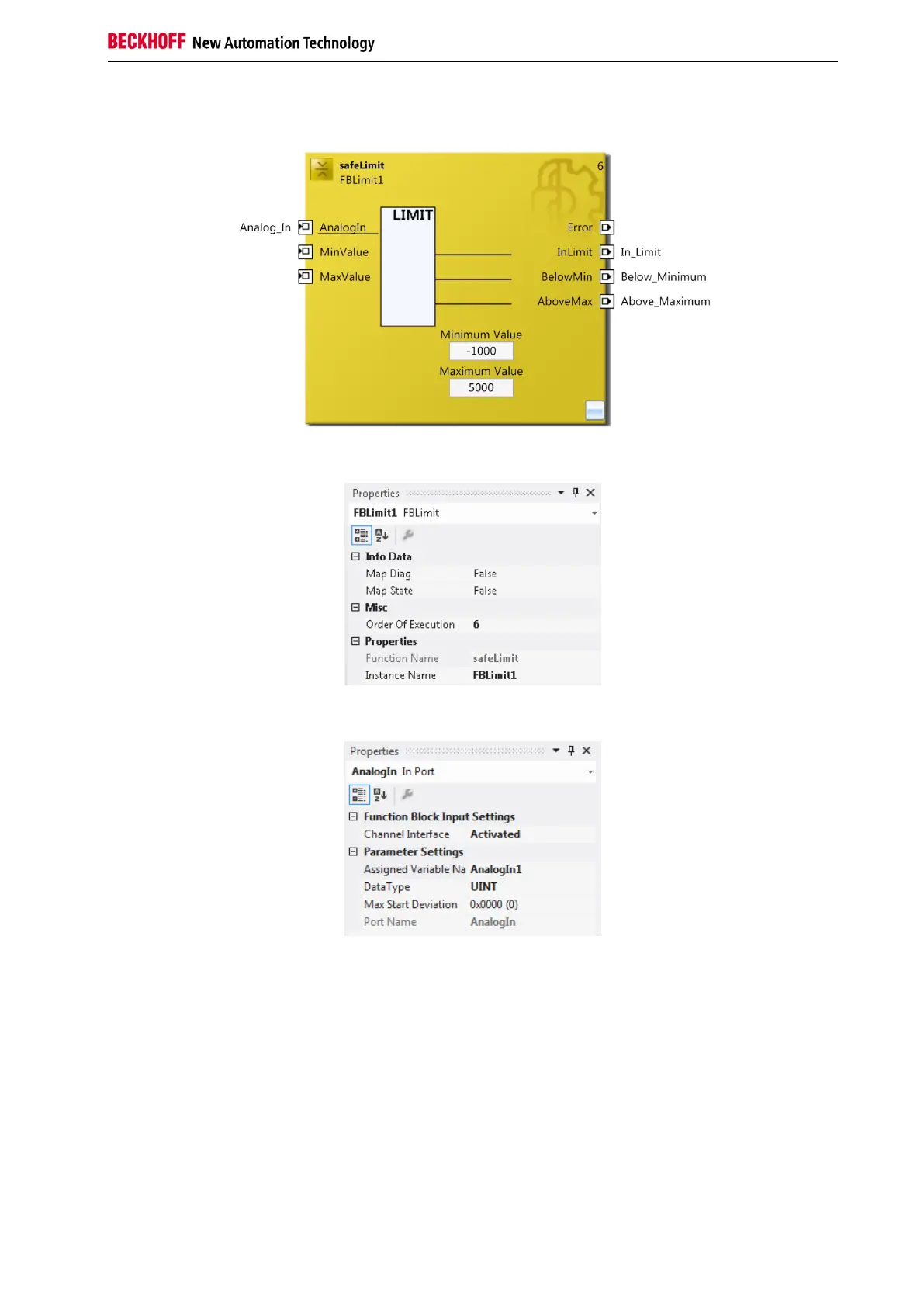
3.21.3 FB LIMIT configuration in TwinCAT 3
Figure 3-89: FB Limit configuration
Figure 3-90: FB Limit properties
Figure 3-91: FB Limit port properties
A mouse click next the FB port, here AnalogIn1, MinValue und MaxValue, can be used to create variables
that can be linked to input signals. Input settings, such as changing the data type or activation of the
input, can be made via the properties of the FB port. Either the FB inputs MinValue and MaxValue or the
parameters Minimum Value and Maximum Value can be used. If the FB inputs are active, they are used.
The MapState and MapDiag entries define which diagnostic functions of the FB are mapped to the cyclic
process image.

 Loading...