Function blocks
28 Function blocks for TwinSAFE logic components
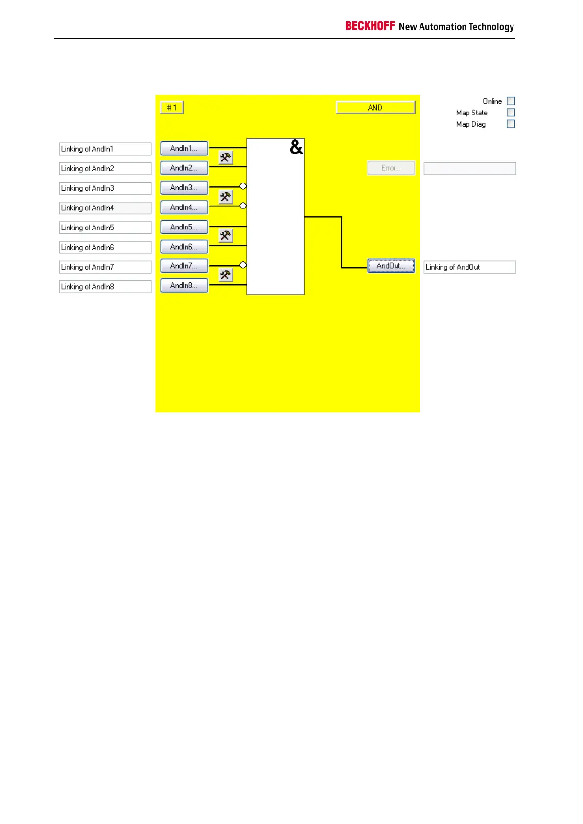
3.1.3 FB AND configuration in the TwinCAT System Manager
Figure 3-2: FB AND configuration
Use the Settings buttons to the right of two AndIn inputs to configure their behavior. The inputs are
always single-channel. A discrepancy monitoring cannot be used for the FB AND.
The 'AndIn(x)' buttons can only be selected if the corresponding input has been activated via the Settings
button. In the default setting all inputs are disabled.
The FB AND input variables are linked using the 'AndIn(x)' buttons.
The output variable of the FB AND are linked using the 'AndOut' button.
The 'MapState' and 'MapDiag' checkboxes are used to specify which FB diagnostic functions are mapped
to the cyclic process image.
The FB AND does not supply any error information and therefore the error button is basically deactivated.

 Loading...