Chapter 9 Maintenance
BES-940BC • BES-1240BC
232
3-3. Lower shaft module
1. Remove the peripheral parts so that the top
of the case cover of the lower shaft can be
seen.
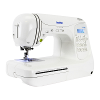
2. Remove the tape covering the notch if the
lower shaft's case cover is notched.
When there is no notch, make one with a
knife.
(Note) Be careful not to make a deep notch to avoid
cutting the harness on the rear of the lower
shaft's case cover.
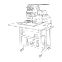
3. Place the cover so that the notch is on the
top as shown in the illustration to the left.
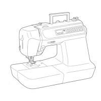
4. Evenly apply the supplied grease tank 30
(white) when the coil spring is engaged with
the edge of the coupling hub F.
(Note) Replace the lower shaft module if the coil
spring is not engaged with the edge j of the
coupling hub F, but is only displaced.
5. Apply the grease between each coil spring
while setting up the supplied driver
between coil springs.
(Note) Be careful not to get any grease on the PCB
or the encoder.
6. Turn the needle gap adjusting screw to let
grease conform to the coil springs.
Coil spring
Section to which grease is applied
Coupling hub F
5 mm
5 mm
35 mm
notch
 Loading...