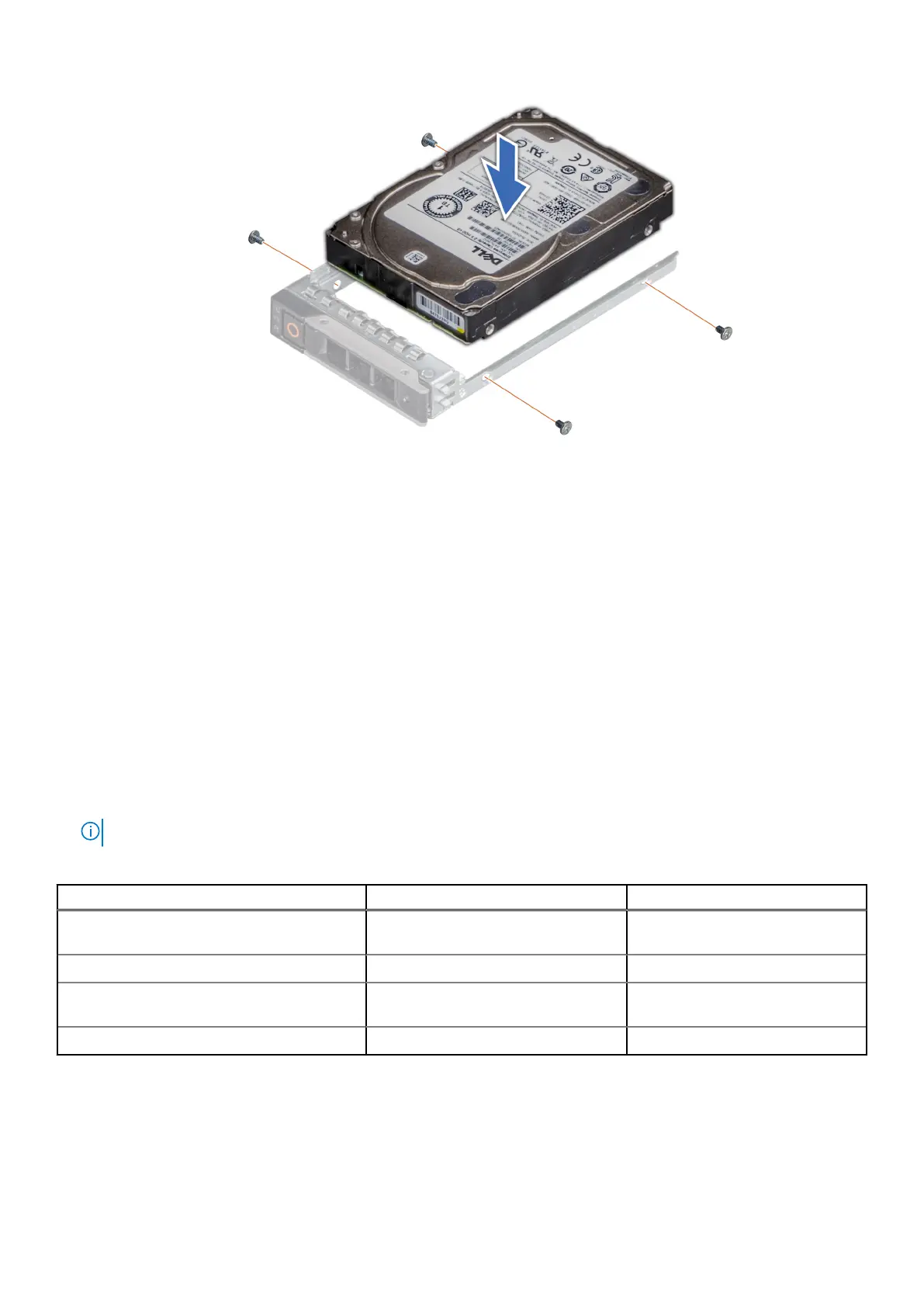
Figure 61. Installing a drive into the drive carrier
Next steps
1. Install the drive carrier.
Rear drive module
Removing the 2 x 2.5-inch rear drive module
Prerequisites
1. Follow the safety guidelines listed in Safety instructions.
2. Follow the procedure listed in Before working inside your system.
3. If required, remove the air shroud.
4. Remove the drives.
5. Disconnect the cables from the rear drive module.
NOTE: Refer to cable routing section for more information.
Table 76. Rear drive bay slot numbers
Configurations with two rear drives Bay0 slot numbers Bay1 slot numbers
12 x 3.5-inch SAS/SATA + 2 x 2.5-inch SAS/
SATA
Slot 0 and 1 N/A
12 x 3.5-inch SAS/SATA + 2 x 2.5-inch NVMe Slot 0 and 1 N/A
24 x 2.5-inch SAS/SATA + 2 x 2.5-inch SAS/
SATA
N/A Slot 24 and 25
24 x 2.5-inch SAS/SATA + 2 x 2.5-inch NVMe Slot 0 and 1 N/A
Steps
1. Using a Phillips #2 screwdriver, loosen the captive screws that secure the rear drive module to the system.
2. Press the blue release tab and holding the edges lift the rear drive module away from the system.
Installing and removing system components
111
 Loading...


