Figure 146. Set the anti-tilt wires to the locked position and tightening the nuts
Next steps
1. Install the air shroud or install the GPU air shroud.
2. Follow the procedure listed in the After working inside your system.
Removing the Direct Liquid Cooling module
Prerequisites
1. Follow the safety guidelines listed in the Safety instructions.
2. Follow the procedure listed in the Before working inside your system.
3. Remove the air shroud or remove the GPU air shroud.
4. Remove the expansion card riser.
WARNING:
The Direct liquid cooling (DLC) module and processor are too hot to touch for some time after the
system has been powered off. Allow the liquid cooling module and processor to cool down before handling them.
NOTE: Rear I/O (RIO) board is different for the system with DLC module.
Steps
1. Using a Phillips #2 screw driver, loosen the captive screw on the DLC ring holder.
2. Tilt the DLC ring holder to loosen the DLC tubes.
3. Disconnect the DLC leak detection cable from the LC RIO board.
4. Remove the DLC tubes from the clip and LC RIO board.
5. Slightly lift the DLC tubes surrounding the DIMM slots.
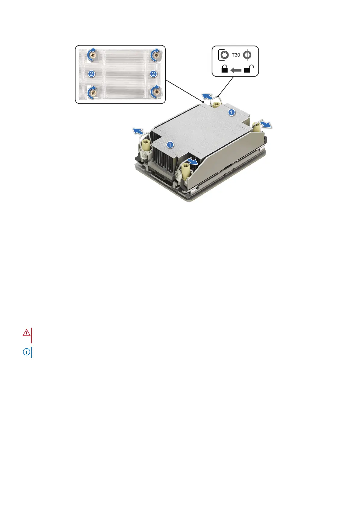
6. Ensure all four anti-tilt wires are in the locked position (outward position), and then using a Torx T30 screwdriver, loosen the
captive nuts on the DLC module in the order that is mentioned below:
a. Loosen the first nut three turns.
b. Loosen the nut diagonally opposite to the nut you loosened first.
c. Repeat the procedure for the remaining two nuts.
d. Return to the first nut and loosen it completely.
190
Installing and removing system components
 Loading...


