Analog and digital I/O lines Configurable I/O pins and configuration commands
XBee/XBee-PRO® S2C ZigBee® RF Module
144
Configurable I/O pins and configuration commands
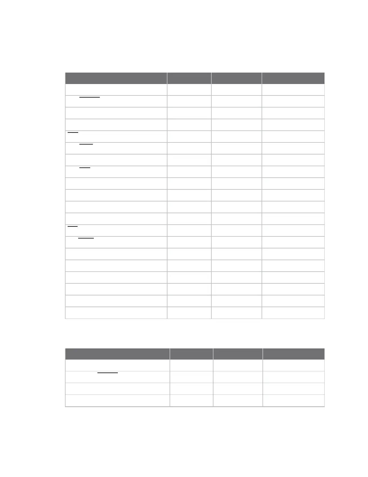
The following tables list the configurable I/O pins and the corresponding configuration commands.
Module Pin Names Module Pin AT Command Command Range
DOUT/DIO13 3
P3
0, 1, 3-5
DIN/
CONFIG
/DIO14 4
P4
0, 1, 3-5
RSSI PWM/DIO10 7
P0
0, 1, 3-5
PWM1/DIO11 8
P1
0, 1, 3-5
DTR
/SLEEP_RQ /DIO8 10
D8
0, 1, 3-5
SPI_
ATTN
/ BOOTMODE/DIO19 12
P9
0, 1, 6
SPI_SClk/DIO18 14
P8
0, 1
SPI_
SSEl
/DIO17 15
P7
0, 1
SPI_MOSI/DIO16 16
P6
0, 1
SPI_MISO/DIO15 17
P5
0, 1
[reserved]* 21
P2
0, 3-5
DIO4 24
D4
0, 3-5
CTS
/DIO7 25
D7
0, 1, 3-7
ON/
SLEEP
/DIO9 26
D9
0, 1, 3-5
ASSOCIATE/DIO5 28
D5
0, 1, 3-5
RTS/DIO6 29
D6
0, 1, 3-5
AD3/DIO3 30
D3
0, 2-5
AD2/DIO2 31
D2
0, 2-5
AD1/DIO1 32
D1
0, 2-6
AD0/DIO0 33
D0
0-5
XBee ZB through-hole RF module
Module Pin Names Module Pin AT Command Command Range
DIO13/DOUT 2
P3
0, 1, 3-5
DIO14/DIN/CONFIG
3
P4
0, 1, 3-5
DIO12/PWM2/SWDIO/SPI_MISO 4
P2
DIO10/PWM RSSI/DAC0 6
P0
0, 1, 3-5

 Loading...


