Hardware Design notes
XBee/XBee-PRO® S2C ZigBee® RF Module
35
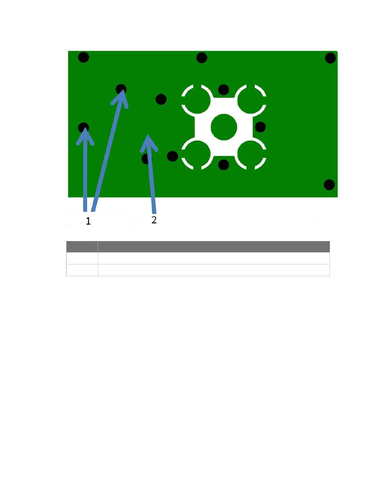
Number Description
1
Use multiple vias to help eliminate ground variations.
2 Put a solid ground plane under RF trace to achieve the desired impedance.
Module operation for the programmable variant
The modules with the programmable option have a secondary processor with 32k of flash and 2k of
RAM. This allows module integrators to put custom code on the XBee module to fit their own unique
needs. The secondary processor intercepts the DIN, DOUT, RTS, CTS, and RESET lines to allow it to be
in control of the data transmitted and received. All other lines are in parallel and can be controlled by
either the EM357 or the MC9SO8QE micro. See the following block diagram for details. The
Programmable XBee SDK native APIs automatically handle pin use.
For the secondary processor to sample with ADCs, the XBee VREF pin (27/SMT, 14/TH) must be
connected to a reference voltage.
Digi provides a bootloader that can take care of programming the processor over-the-air or through
the serial interface. This means that over-the-air updates can be supported through an XMODEM
protocol. The processor can also be programmed and debugged through a one wire interface BKGD
(Pin 9/SMT, Pin 8/TH).

 Loading...


