Hardware Pin signals for the through-hole module
XBee/XBee-PRO® S2C ZigBee® RF Module
26
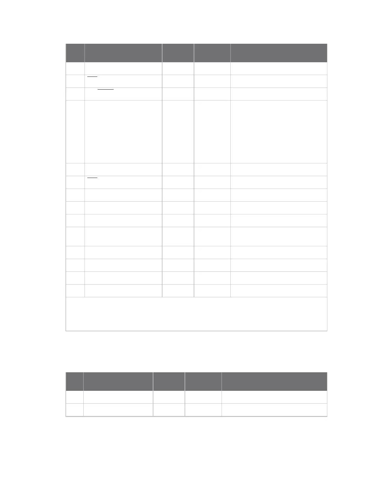
Pin# Name Direction
Default
state Description
24 DIO4 Both Disabled GPIO
25 CTS/DIO7 Both Output Clear to send flow control/GPIO
26 ON/SLEEP/DIO9 Both Output Device status indicator/GPIO
27 VREF Input -
Not used for EM357. Used for
programmable secondary
processor. For compatibility with
other XBee devices, we
recommend connecting this pin to
the voltage reference if analog
sampling is desired. Otherwise,
connect to GND.
28 ASSOCIATE/DIO5 Both Output Associate Indicator/GPIO
29 RTS/DIO6 Both Input Request to send flow control /GPIO
30 AD3/DIO3 Both Disabled Analog input/GPIO
31 AD2/DIO2 Both Disabled
Analog input/GPIO
32 AD1/DIO1 Both Disabled
Analog input/GPIO
33 AD0 /DIO0 Both Input Analog input / GPIO /
Commissioning button
34 [reserved] - Disabled Do not connect
35 GND - - Ground
36 RF Both - RF I/O for RF pad variant
37 [reserved] - Disabled Do not connect
Signal direction is specified with respect to the device.
See Design notes for details on pin connections.
* Refer to Writing custom firmware for instructions on using these pins if JTAG functions are needed.
Pin signals for the through-hole module
The following table shows the pin signals and their descriptions for the through-hole module.
Pin
# Name Direction
Default
state Description
1 VCC - - Power supply
2 DOUT/DIO13 Both Output UART data out

 Loading...


