Module support Writing custom firmware
XBee/XBee-PRO® S2C ZigBee® RF Module
264
ModuleIsXBeePro = true;
} else {
ModuleIsXBeePro = false;
}
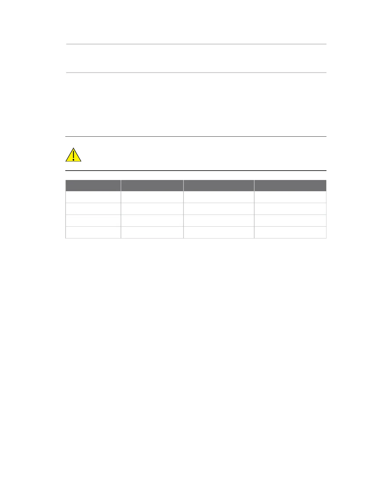
Special instructions for using the JTAG interface
There are four JTAG programming pins on the XBee/XBee-PRO ZigBee RF Module through which
firmware can be loaded onto the EM357 processor. Three of these pins are also connected to a second
pin on the device and are used for separate functions. The following table indicates the JTAG signal
name, the primary connection pin on the device, the secondary connection pin, and the secondary
signal name.
CAUTION! Do not load the secondary pins with circuitry that might interfere with JTAG
programming (for example, an LED tied directly to the ASSOCIATE / DIO5 line). Any
loading circuitry should be buffered to avoid conflicts (for example, connecting
ASSOCIATE / DIO5 to the gate of a MOSFET which drives the LED).
JTAG pin name Primary XBee pin Secondary XBee pin Secondary pin name
JTCK 18 N/A N/A
JTDO 19 26 ON / SLEEP / DIO9
JTDI 20 28 ASSOCIATE / DIO5
JTMS 21 5 DIO12