Hardware EM357 pin mappings
XBee/XBee-PRO® S2C ZigBee® RF Module
27
Pin
# Name Direction
Default
state Description
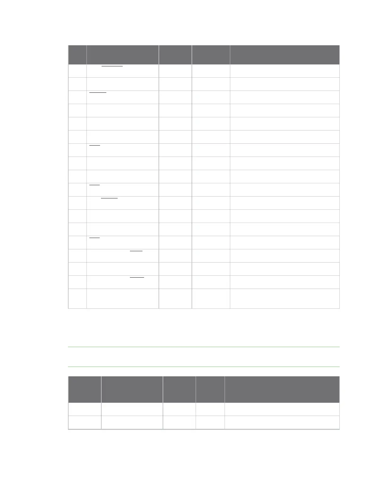
3 DIN/CONFIG / DIO14 Both Input UART data in
4 DIO12/SPI_MISO Both Disabled GPIO/SPI slave out
5 RESET Input Input Module reset
6 RSSI PWM/PWMO DIO10 Both Output RX signal strength indicator/GPIO
7 PWM1/DIO11 Both Disabled GPIO
8 [reserved] - - Do not connect
9 DTR/SLEEP_RQ/ DIO8 Both Input Pin sleep control line/GPIO
10 GND - - Ground
11 SPI_MOSI/DIO4 Both Disabled GPIO/SPI slave in
12 CTS/DIO7 Both Output Clear-to-send flow control/GPIO
13 ON_SLEEP/DIO9 Both Output Device status indicator/GPIO
14 VREF - - Not connected
15 ASSOCIATE/DIO5 Both Output Associate indicator/GPIO
16 RTS/DIO6 Both Input Request to send flow control/ GPIO
17 AD3/DIO3/SPI_SSEL Both Disabled Analog input/GPIO/SPI slave select
18 AD2 / DIO2/SPI_CLK Both Disabled Analog input/GPIO/SPI clock
19 AD1/DIO1/SPI_ATTN Both Disabled Analog input/GPIO/SPI attention
20 AD0/DIO0/CB Both Disabled Analog input/GPIO/ Commissioning
button
EM357 pin mappings
The following table shows how the EM357 pins are used on the device.
Note Some lines may not go to the external device pins in the programmable secondary processor
version.
EM357
pin# EM357 pin name
XBee
(SMT)
pad#
XBee
(TH)
pin # Other usage
12 RST 6 5 Programming
18 PA7 8 7

 Loading...


