MES1000, MES2000 Ethernet Switches 25
2.4.5 MES2124P series device panel appearance and layout
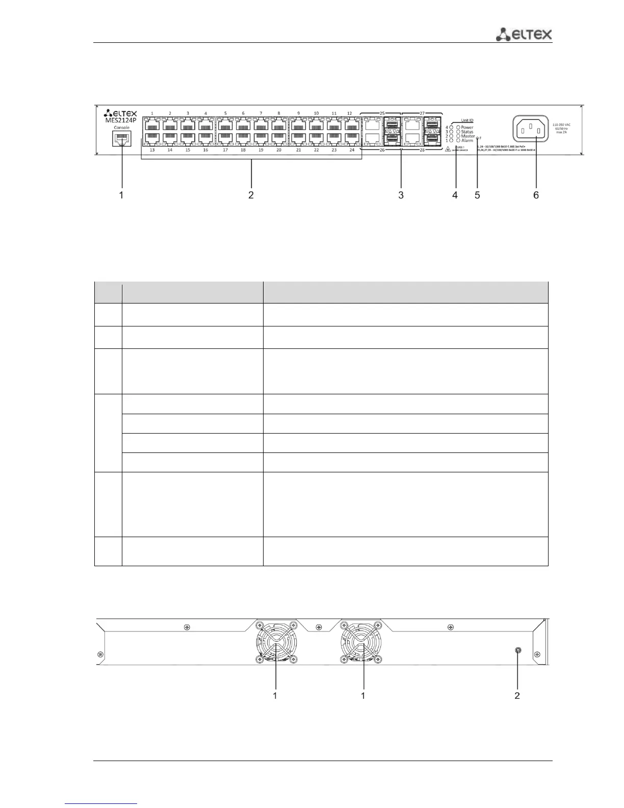
Front panel layout MES2124P is depicted in Fig. 13.
Fig. 13— MES2124P, front panel
Table 2.14 lists sizes, LEDs and controls located on the front panel of the switch.
Table 2.14 —Description of connectors, LEDs and controls located on the front panel MES2124P
RS-232 console port for local control of the device.
24 ports 10/100/1000 Base-T (RJ-45 with support for PoE+)
Combo ports: 10/100/1000 Base-T (RJ45) ports and slots for
1000Base-X (SFP) transceiver installations
Indicator of device number in a stack
PoE power supply indicator
Functional key that reboots the device and resets it to factory
settings:
- pressing the key for less than 10 seconds reboots the device.
- pressing the key for more than 10 seconds resets the terminal to
factory settings.
~150-250VAC, 60/50Hz
max 2A
Connector for AC power supply
The rear panel layout of MES2124P series switches is depicted in Fig. 14.
Fig. 14—Rear panel of MES2124P
Table 2.13 lists rear panel connectors of the switch.
 Loading...