32 MES1000, MES2000 Ethernet Switches
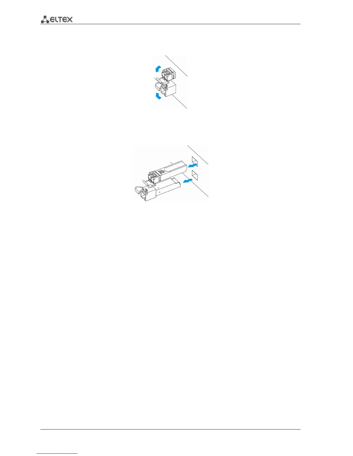
To remove a transceiver, perform the following actions:
1. Unlock the module's latch.
Fig. 25—Opening SFT transceiver latch
2. Remove the module from the slot.
Fig 26—SFP transceiver removal
3.5 Connection to Power Supply
To install the device:
1. Mount the device. In case of installation to a 19" form-factor rack, mount the support
brackets from the delivery package to the rack (see Paragraph 3.1).
2. Ground the case of the device. This should be done prior to connecting the device to the
power supply. An insulated multiconductor wire should be used for earthing. The device
grounding and the earthing wire cross-section should comply with Electric Installation Code.
3. If a PC or another device is supposed to be connected to the switch console port, the device
should be also securely grounded.
4. Connect the power supply cable to the device. Depending on the switch model, the device
can be powered by AC 220V 50/60Hz or DC 48V electrical network. To connect the device to
AC power supply, use the cable from the delivery package. To connect the device to DC
power supply, use the cable with cross-section not less than 1mm
2
.
5. Turn the device on and check the front panel LEDs to make sure the terminal is in normal
operating conditions.
 Loading...