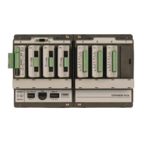
S600 Instruction Manual
Chapter 4 – Input/Output (I/O)
This chapter provides information on plug-in connector blocks and
field wiring (ANIN, PRT, and DPR signals).
In This Chapter
4.1 P144 I/O Board ...................................................................................4-1
4.1.1 Analogue Inputs (ANIN)......................................................... 4-3
4.1.2 Analogue Outputs (DAC).......................................................4-5
4.1.3 Digital Inputs (DIGIN).............................................................4-6
4.1.4 Digital Outputs (DIGOUT)......................................................4-8
4.1.5 Turbine Pulse Inputs..............................................................4-9
4.1.6 Pulse Outputs (PULSEOUT) ...............................................4-10
4.1.7 Raw Pulse Output (RAWOUT) ............................................4-11
4.1.8 Frequency Inputs.................................................................4-12
4.1.9 PRT/RTD Inputs ..................................................................4-13
4.1.10 P144 I/O Bit Links (Jumpers)............................................... 4-14
4.2 P154 Prover Board ...........................................................................4-16
4.2.1 Digital Inputs (DIGIN)...........................................................4-18
4.2.2 Digital Outputs (DIGOUT)....................................................4-20
4.2.3 Turbine Pulse Inputs............................................................4-21
4.2.4 Pulse Outputs (PULSEOUT) ...............................................4-22
4.2.5 Frequency Inputs.................................................................4-22
4.2.6 P154 Prover Bit Links (Jumpers)......................................... 4-24
4.3 P188 HART Board............................................................................4-25
Perform all wiring with stranded wire no larger than 1.75mm
2
. Observe
all local wiring practices and regulations.
Caution
Do not use a Mega or similar instrument to check for isolation or
continuity between signals on any of the S600 connectors. These
instruments produce voltages far in excess of design parameters and
may damage the S600.
4.1 P144 I/O Board
The P144 I/O board measures process signals the CPU uses while
running the flow computer functions. The I/O board is comprised of 12
analogue inputs (AI) , 4 analogue outputs (AO), 16 digital inputs (DI) ,
12 digital outputs (DO), 4 pulse inputs (PI), 5 pulse outputs (PO), 3
frequency (density) inputs, and 3 PRT/RTD inputs. Refer to Figure 4-2
for the P144 I/O board terminations.
For field wiring, the S600 backplate provides three low-density D-type
connectors labeled SKT-A, SKT-B, and SKT-C (refer to Figure 4-1).
Revised Jan-07 I/O 4-1
 Loading...
