S600 Instruction Manual
Table 4-10. Raw Pulse Output Pin Connections for SKT-C
Pin Function
24 Raw Output
5 Return
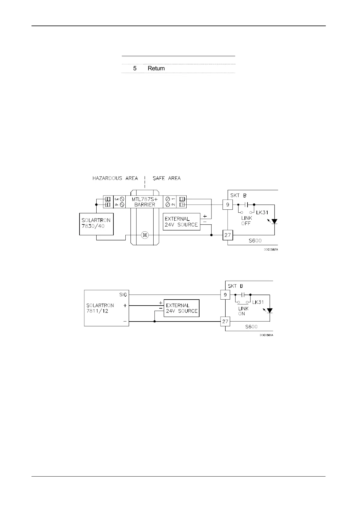
4.1.8 Frequency Inputs
The S600 typically uses the three supported frequency inputs for
density transducer signals. Each input has an input range of 0 to 10
KHz. Bit links are provided to allow the inputs to be AC- or DC-
coupled. Refer to Figures 4-17 and 4-18.
The frequency input channels use the SKT-B connector, which is
located on the backplate of the P144 board. Table 4-11 shows the
frequency input pin connections.
Figure 4-17. Frequency Input Schematic (with IS Barrier and AC-Coupled)
Figure 4-18. Frequency Input Schematic (without IS Barrier and with DC-Coupled)
4-12 I/O Revised Jan-07
 Loading...


