S600 Instruction Manual
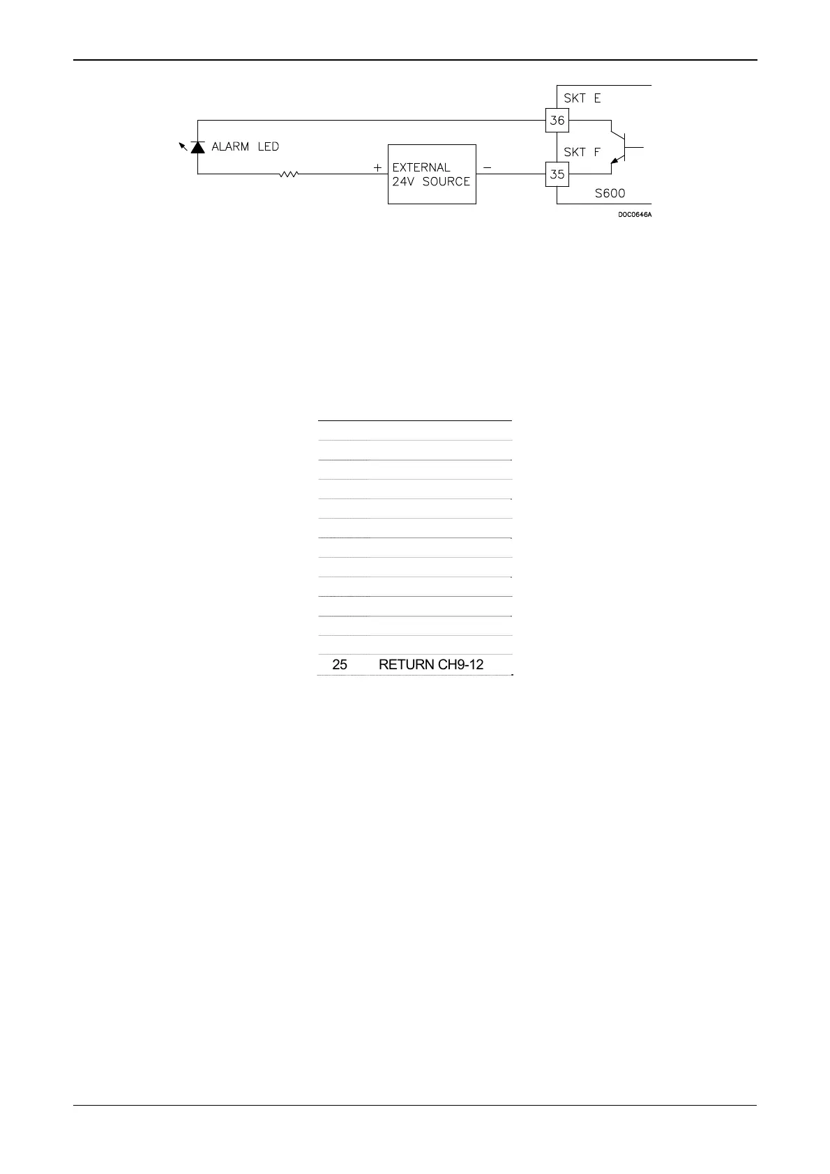
Figure 4-26. Digital Output Schematic (24 V Switched Indicator)
Table 4-17. DIGOUT Pin Connections for SKT-E
Pin Function
36 DIGOUT-CH1
37 DIGOUT-CH2
Table 4-18. DIGOUT Pin Connections for SKT-F
Pin Function
37 DIGOUT-CH3
36 DIGOUT-CH4
35 RETURN CH1-4
34 DIGOUT-CH5
33 DIGOUT-CH6
32 DIGOUT-CH7
31 DIGOUT-CH8
30 RETURN CH5-8
29 DIGOUT-CH9
28 DIGOUT-CH10
27 DIGOUT-CH11
26 DIGOUT-CH12
25 RETURN CH9-12
4.2.3 Turbine Pulse Inputs
You can use the four pulse inputs either independently or as two pairs.
Generally, they are used for dual pulse measurement, such as turbine
applications. In dual pulse mode, you can enable level A or B pulse
checking.
Each input has an input range of 1 to 10 KHz. Each channel has live
integrity checking. If cabling faults develop or if the pre-amp power
fails, the system activates a circuit fail alarm.
Table 4-19 shows the dual-pulse input pin connections. Refer to Figure
4-27 for field wiring schematics.
Revised Jan-07 I/O 4-21
 Loading...


