S600 Instruction Manual
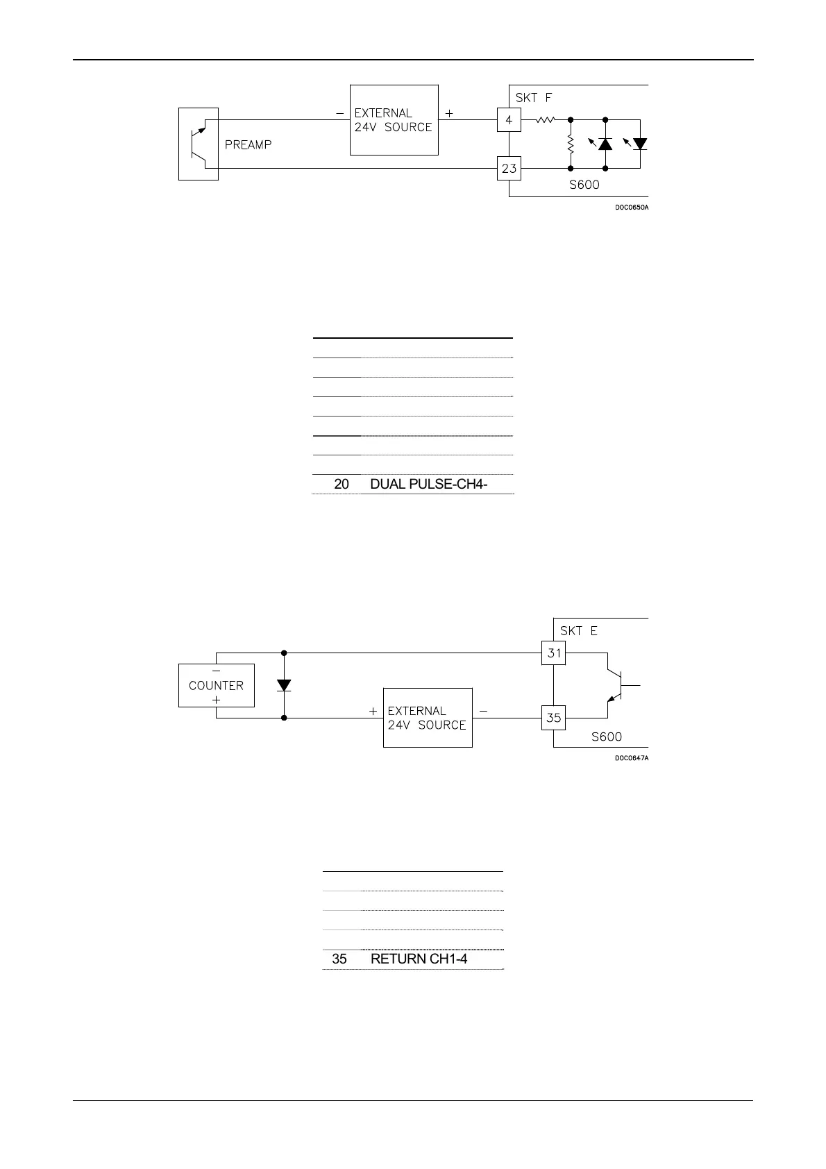
Figure 4-27. Pulse Input Schematic (with US 24 V P148 Mezzanine
Card)
Table 4-19. Dual-Pulse Input Pin Connections for SKT-F
Pin Function
4 DUAL PULSE-CH1+
23 DUAL PULSE-CH1-
3 DUAL PULSE-CH2+
22 DUAL PULSE-CH2-
2 DUAL PULSE-CH3+
21 DUAL PULSE-CH3-
1 DUAL PULSE-CH4+
20 DUAL PULSE-CH4-
4.2.4 Pulse Outputs (PULSEOUT)
The S600 provides four programmable pulse outputs, typically used for
electronic counters. Refer to Table 4-20 for the PULSEOUT pin
connections. Refer to Figure 4-28 for field wiring schematics.
Figure 4-28. Pulse Output Schematic
Table 4-20. PULSEOUT Pin Connections for SKT-E
Pin Function
31 PULSEOUT-CH1
32 PULSEOUT-CH2
33 PULSEOUT-CH3
34 PULSEOUT-CH4
35 RETURN CH1-4
4.2.5 Frequency Inputs
The S600 supports two frequency inputs, typically used for density
transducer signals. Each input has an input range of 0 to 10 KHz.
4-22 I/O Revised Jan-07
 Loading...


