Setup & Operation 3. Environment and Installation
S5 Rev.5 33
Removal
Remove the bolts combining
the shipping jigs at the point A.
-M5×14 hexagon socket head cap bolts with plain washers and disc spring washers
securing the shipping jigs at the point B. Then, remove the upper
s.
-M6×10 hexagon socket head cap bolts with plain washers and disc spring washers
Before turning on the power, be sure that the shipping bolts and jigs have been removed.
The shipping bolts and jigs must then be stored for future use, in the event that the
Manipulator must be moved again.
Installation
sition the Manipulator as show in the figure above.
2)
Attach the upper part of the shipping jigs to the Manipulator at the point
B
. Secure
it with the bolts.
-M6×10 hexagon socket head cap bolts with plain washers and disc spring washers
3)
Secure the shipping jigs at the point
A with the bolts.
-M5×14 hexagon socket head cap bolts with plain washers and disc spring washers
3.2.4 Relocating
Follow the procedures described below when relocating the Manipulator.
for all devices and unplug the cables.
Remove the mechanical stops if using them to limit the motion range
.
n the motion range, refer to the Setup & Operation 5.2
Motion Range
Setting of Arm #
1 by Mechanical Stops.
.
Then, remove the Manipulator from the base table.
ition
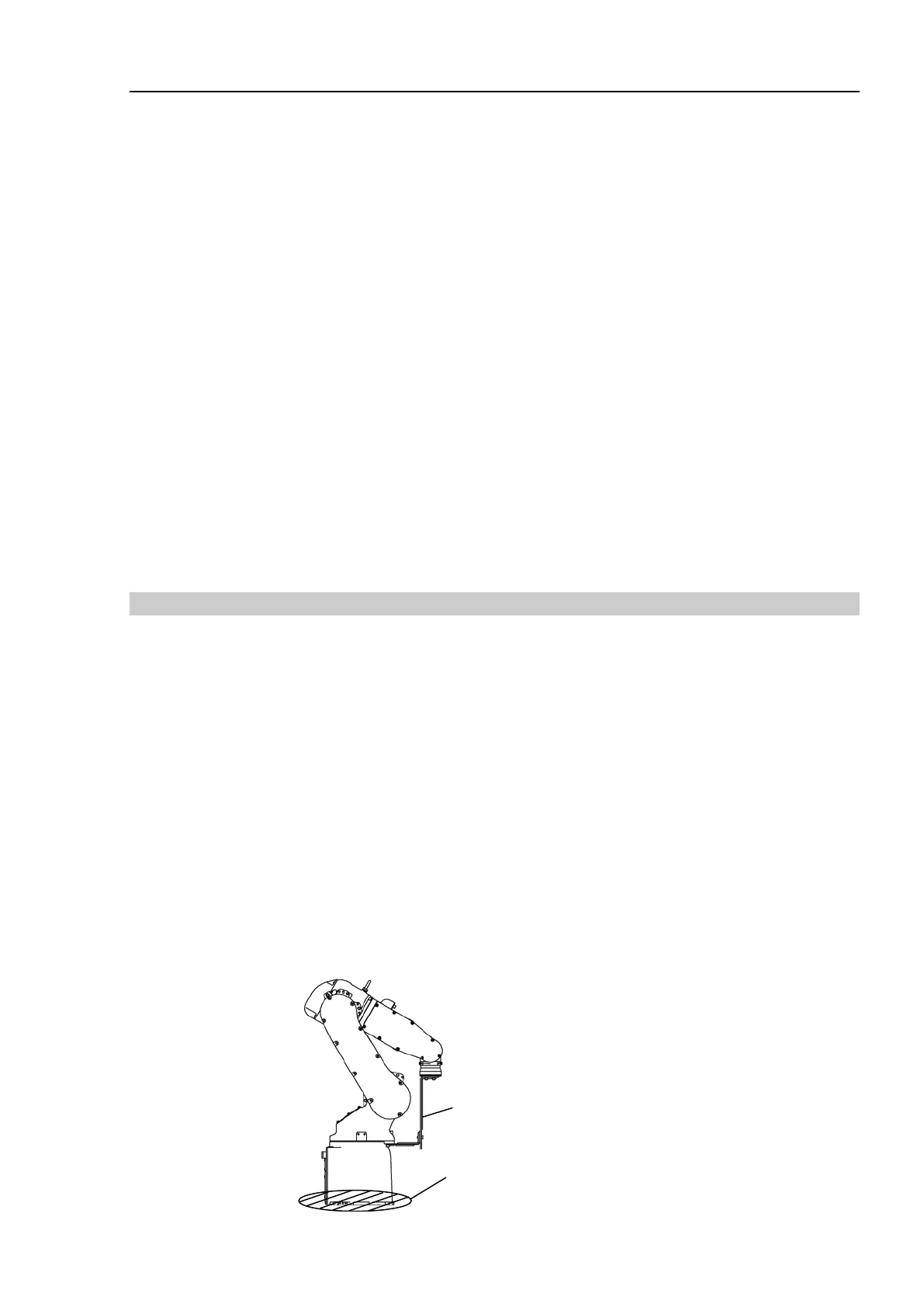
the Manipulator as shown in the figure. Then, secure the Manipulator to
the delivery equipment or have three or more people to carry the Manipulator.
Do not hold the bottom of the base (the screened parts in the figure). Holding these
parts by hand is
extremely hazardous and may cause your hands and fingers to be
caught or cut by the
grounding electrode.
S5-A701**
Approx. 38 kg (Manipulator weight: 36 kg (80 lb.))
S5-A901**
Approx. 40 kg (Manipulator
weight: 38 kg (84 lb.))
DO NOT hold
the bottom of the
base by hand.
 Loading...


