114
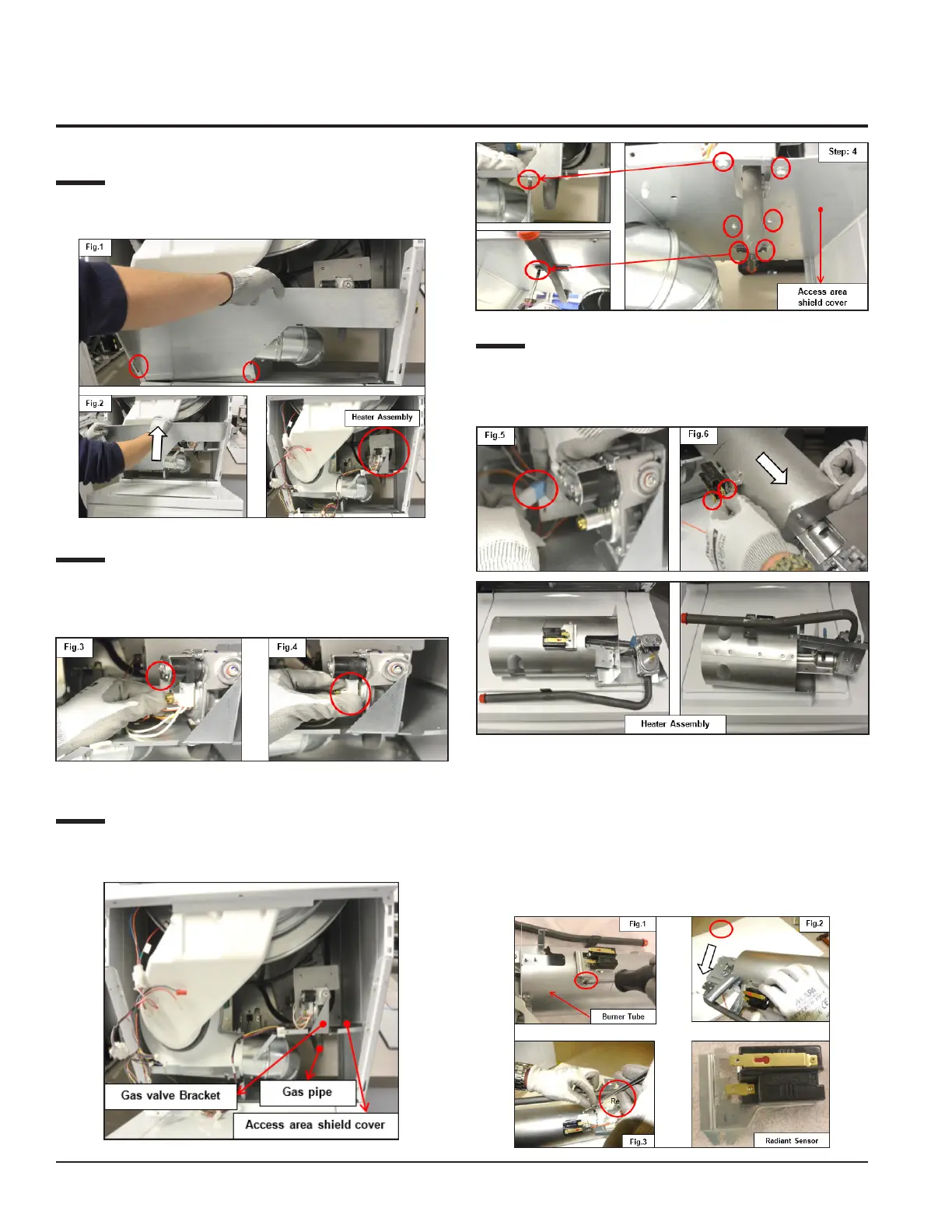
Step: 2
Slide and pull out the LCD Support Cover as shown in Figs.
1 and 2.
Step: 3
Detach the connectors from the Solenoid Gas valve, that is
Secondary coil, Booster coil, Figs. 3 and 4.
Step: 4
Loosen the Gas valve Bracket screws (4) and Gas pipe
screws (2) which are fixed with the Access area shield cover.
Step: 5
Detach the connector (See Fig. 5) and pull out the Heater
Assembly. Then detach the Radiant Sensor terminals (2) (See
Fig. 6) while taking the Gas Assembly outside.
11.8.1 Radiant / Flame Sensor
Accessibility
Remove the screw (See Fig.1) of the Radiant Sensor that
fits with the Burner Tube. Also remove the clamp (See Fig.
2) and then detach the terminals (See Fig. 3) to separate the
Radiant Sensor.
 Loading...