7-6 469 Motor Management Relay GE Power Management
7.2 HARDWARE FUNCTIONAL TESTING 7 TESTING
7
7.2.6 DIGITAL INPUTS AND TRIP COIL SUPERVISION
The digital inputs and trip coil supervision can be verified easily with a simple switch or pushbutton. Verify the
SWITCH +24 V DC with a voltmeter. Perform the steps below to verify functionality of the digital inputs.
1. Open switches of all of the digital inputs and the trip coil supervision circuit.
2. View the status of the digital inputs and trip coil supervision in:
A1 STATUS\DIGITAL INPUTS
3. Close switches of all of the digital inputs and the trip coil supervision circuit.
4. View the status of the digital inputs and trip coil supervision in:
A1 STATUS\DIGITAL INPUTS
7.2.7 ANALOG INPUTS AND OUTPUTS
The 469 specification for analog input and analog output accuracy is
±
1% of full scale. Perform the steps below
to verify accuracy. Verify the Analog Input +24 V DC with a voltmeter.
a) 4-20 mA
1. Alter the following setpoints:
S12 ANALOG I/O\ANALOG INPUT1\ANALOG INPUT1: 4-20 mA
S12 ANALOG I/O\ANALOG INPUT1\ANALOG INPUT1 MINIMUM: 0
S12 ANALOG I/O\ANALOG INPUT1\ANALOG INPUT1 MAXIMUM: 1000 (repeat for analog inputs 2 to 4)
2. Analog output values should be
±
0.2 mA on the ammeter. Measured analog input values should be
±
10
units. Force the analog outputs using the following setpoints:
S13 TESTING\TEST ANALOG OUTPUT\FORCE ANALOG OUTPUTS FUNCTION: Enabled
S13 TESTING\TEST ANALOG OUTPUT\ANALOG OUTPUT 1 FORCED VALUE: 0%
(enter desired percent, repeat for analog outputs 2 to 4)
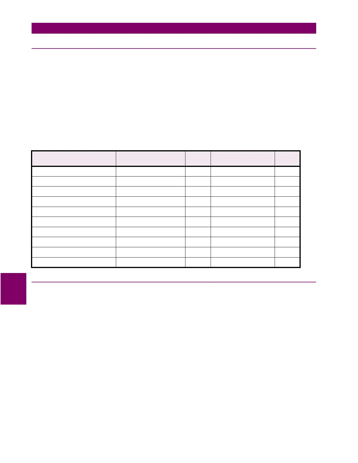
Table 7–10: DIGITAL INPUTS
INPUT EXPECTED STATUS
(SWITCH OPEN)
PASS /
FAIL
EXPECTED STATUS
(SWITCH CLOSED)
PASS /
FAIL
ACCESS Open Shorted
TEST Open Shorted
STARTER STATUS Open Shorted
EMERGENCY RESTART Open Shorted
REMOTE RESET Open Shorted
ASSIGNABLE INPUT 1 Open Shorted
ASSIGNABLE INPUT 2 Open Shorted
ASSIGNABLE INPUT 3 Open Shorted
ASSIGNABLE INPUT 4 Open Shorted
TRIP COIL SUPERVISION No Coil Coil
 Loading...