Home
GE
Relays
469
GE 469 Manual
5
of 1
of 1 rating
307 pages
Give review
Manual
Specs
To Next Page
To Next Page
To Previous Page
To Previous Page
Loading...
GE Power M
anagement
469 Mo
tor Managemen
t Relay
D-3
APPENDIX D
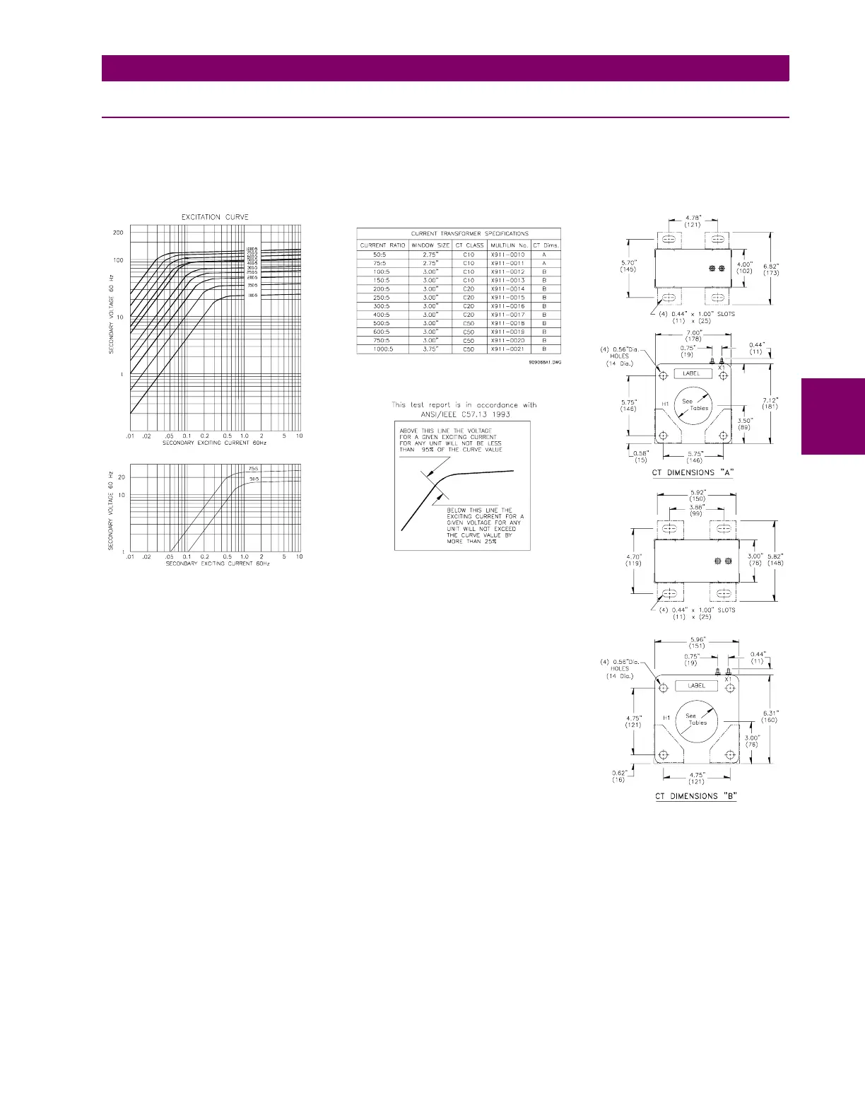
D.1 CURRENT TRANSFORM
ERS
D
D.1.3 PHASE CTS
Current t
ransformer
s in mos
t common rati
os from 5
0:5 to 100
0:5 are av
ailable f
or use as pha
se cu
rrent in
puts
with motor pr
otection rela
ys. Thes
e come with mounti
ng hardwar
e and are also avail
able with 1 A seco
ndaries
.
V
oltage
class
: 600
V BIL 10 kV
.
288
290
Table of Contents
Table of Contents
1
Introduction
9
Overview
9
Description
9
Order Information
12
Other Accessories
12
Specifications
13
Setpoint
13
Installation
19
Mechanical
19
Description
19
Product Identification
20
Installation
20
Unit Withdrawal and Insertion
22
Terminal Locations
24
Electrical
26
Typical Wiring Diagram
26
Typical Wiring
27
Control Power
27
Phase Current Inputs
28
Ground Current Input
28
Differential Current Inputs
30
Voltage Inputs
31
Digital Inputs
31
Analog Inputs
32
Analog Outputs
32
Rtd Sensor Connections
33
Description
33
Reduced Rtd Lead Number Application
34
Two Wire Rtd Lead Compensation
35
GROUNDING of Rtds
35
Output Relays
36
Drawout Indicator
37
Rs485 Communications Ports
38
Typical 2 Speed Motor Wiring
39
Dielectric Strength Testing
40
Operation
41
Overview
41
Faceplate
41
Display
42
Led Indicators
42
A 469 STATUS LED INDICATORS
42
Motor Status Led Indicators
43
Output Relay Led Indicators
43
Rs232 Program Port
43
Keypad
44
Entering Alphanumeric Text
44
Entering +/- Signs
44
Setpoint Entry
45
Procedure
45
Trips/Alarms/Blocks Defined
47
Trips
47
Alarms
47
Relay Assignment Practices
48
Setpoint Message Map
49
S1 469 Setup
50
Passcode
50
Function
50
Enabling Passcode Protection
50
Preferences
51
Serial Ports
52
Real Time Clock
52
Default Messages
53
Adding Default Messages
53
Removing Default Messages
53
Message Scratchpad
54
Clear Data
55
Installation
56
S2 System Setup
57
Current Sensing
57
Function
57
Examples
58
Voltage Sensing
58
Power System
59
Serial Communication Control
59
Reduced Voltage
60
S3 Digital Inputs
62
Description
62
Access Switch
62
Test Switch
62
Emergency Restart
62
Remote Reset
62
Starter Status
63
Assignable Digital Inputs
63
Digital Input Function: Remote Alarm
64
Digital Input Function: Remote Trip
64
Digital Input Function: Speed Switch Trip
65
Digital Input Function: Load Shed Trip
65
Digital Input Function: Pressure Switch Alarm
65
Digital Input Function: Pressure Switch Trip
66
Digital Input Function: Vibration Switch Alarm
66
Digital Input Function: Vibration Switch Trip
66
Digital Input Function: Digital Counter
67
Function
67
Example
67
Function
68
Example
68
Digital Input Function: General Switch A-D
69
Digital Input Function: Capture Trace
69
Digital Input Function: Simulate Pre-Fault
69
Digital Input Function: Simulate Fault
69
S4 Output Relays
70
Description
70
Relay Reset Mode
70
Example
70
Force Output Relay
71
S5 Thermal Model
72
Motor Thermal Limits
72
Thermal Model
74
Overload Curve Setup
75
Function
77
Custom Overload Curve
83
Unbalance Bias
88
Motor Cooling
89
Hot/Cold Curve Ratio
90
Rtd Bias
90
S6 Current Elements
92
Short Circuit
92
Overload Alarm
93
Mechanical Jam
93
Undercurrent
94
Function
94
Example
94
Current Unbalance
95
Function
95
Example
95
Ground Fault
96
Phase Differential
98
S7 Motor Starting
99
Acceleration Timer
99
Start Inhibit
100
Function
100
Example
100
Jogging Block
101
Function
101
Starts / Hour
101
Time between Starts
101
Restart Block
102
S8 Rtd Temperature
103
Rtd Types
103
Rtds 1 to 6
104
Rtds 7 to 10
105
Rtd 11
106
Rtd 12
107
Open Rtd Sensor
108
Rtd Short/Low Temp
108
S9 Voltage Elements
109
Undervoltage
109
Overvoltage
110
Phase Reversal
110
Frequency
111
S10 Power Elements
112
Power Measurement Conventions
112
Power Factor
113
Reactive Power
114
Underpower
115
Function
115
Example
115
Reverse Power
116
Torque Setup
117
Overtorque Setup
117
S11 Monitoring
118
Trip Counter
118
Starter Failure
118
Current, Kw, Kvar, Kva Demand
120
Pulse Output
122
S12 Analog I/O
123
Analog Outputs 1 to 4
123
Analog Output Table
124
Analog Inputs 1-4
125
Function
126
Analog in Diff 3-4
128
S13 469 Testing
129
Simulation Mode
129
Pre-Fault Setup
130
Fault Setup
131
Test Output Relays
132
Test Analog Output
132
Comm Port Monitor
133
Multilin Use Only
133
S14 Two-Speed Motor
134
Description
134
Speed2 O/L Setup
134
Speed2 Undercurrent
136
Speed2 Acceleration
137
Actual Values
139
Overview
139
Actual Values Messages
139
A1 Status
140
Motor Status
140
Last Trip Data
141
Alarm Status
143
Start Blocks
145
Digital Inputs
146
Real Time Clock
146
A2 Metering Data
147
Current Metering
147
Temperature
148
Voltage Metering
149
Speed
149
Power Metering
150
Torque Alarm Message
150
Demand Metering
151
Analog Inputs
152
Phasors
153
A3 Learned Data
155
Motor Starting
155
Average Motor Load
155
Rtd Maximums
156
Analog in Min/Max
157
A4 Maintenance
158
Trip Counters
158
General Counters
160
Timers
160
A5 Event Recorder
161
Event01 to Event40
161
A6 Product Info
164
Model Info
164
Calibration Info
164
Diagnostics
165
Diagnostic Messages for Operators
165
Example
165
Flash Messages
166
Communications
169
Modbus Communications
169
Electrical Interface
169
Modbus Rtu Protocol
169
Data Frame Format and Data Rate
169
Data Packet Format
170
Algorithm
171
Timing
171
Supported Modbus Functions
172
Overview
172
Function Codes 01/02: Read Relay Coil / Digital Input Status
172
Function Codes 03/04: Read Setpoints/Actual Values
176
Function Code 05: Execute Operation
177
Function Code 06: Store Single Setpoint
178
Function Code 07: Read Device Status
179
Function Code 08: Loopback Test
180
Function Code 16: Store Multiple Setpoints
181
Function Code 16: Performing Commands
182
Error Responses
183
Description
183
Memory Map
184
Memory Map Information
184
User Definable Memory Map Area
184
Event Recorder
185
Waveform Capture
185
Memory Map
185
Memory Map Format Codes
229
Testing
237
Overview
237
Test Setup
237
Hardware Functional Testing
238
Phase Current Accuracy Test
238
Voltage Input Accuracy Test
238
Ground (1A/5A) and Differential Accuracy Test
239
A 5 a INPUT
239
B 1 a INPUT
239
Ge Power Management 50:0.025 Ground Accuracy Test
240
Rtd Accuracy Test
240
Digital Inputs and Trip Coil Supervision
242
Analog Inputs and Outputs
242
Output Relays
244
Additional Functional Testing
245
Overload Curve Test
245
Power Measurement Test
246
Unbalance Test
247
Voltage Phase Reversal Test
248
Short Circuit Test
249
Installation/Upgrade
251
Description
251
Hardware & Software Requirements
251
Checking if Installation/Upgrade Is Required
252
Installing/Upgrading 469Pc
253
Configuration
254
Startup & Communications Configuration
254
Using 469Pc
255
Saving Setpoints to a File
255
Firmware Upgrades
256
Loading Setpoints from a File
257
Entering Setpoints
258
Upgrading Setpoint Files to New Revision
259
Waveform Capture
263
Phasors
265
Event Recording
266
Troubleshooting
267
Commissioning Summary
269
Appendix B B.1 Two-Phase Ct Configuration
283
Description
283
Example
285
Current Transformers
287
Ground Fault Cts for 50:0.025 a
287
Ground Fault Cts for 5 a Secondary Ct
288
Phase Cts
289
Figures and Tables
292
List of Tables
293
Eu Declaration of Conformity
295
Warranty Information
297
Warranty
297
Other manuals for GE 469
Instruction Manual
336 pages
Communications Guide
150 pages
5
Based on 1 rating
Ask a question
Give review
Questions and Answers:
Need help?
Do you have a question about the GE 469 and is the answer not in the manual?
Ask a question
GE 469 Specifications
General
Model
GE 469
Category
Relays
Frequency
50/60 Hz
Protection Functions
Overcurrent
Communication Protocols
Modbus, DNP3, IEC 61850
Display
LCD
Mounting
Panel
Related product manuals
GE Multilin 469
64 pages
GE MOTOR MANAGEMENT RELAY 469
311 pages
GE 489
306 pages
GE Multilin 489
314 pages
GE T60
770 pages
GE L90
900 pages
GE D30
686 pages
GE 345
82 pages
GE IAC
32 pages
GE B90
510 pages
GE P642
592 pages
GE MiCOM P40
962 pages

 Loading...