2-22 469 Motor Management Relay GE Power Management
2.2 ELECTRICAL 2 INSTALLATION
2
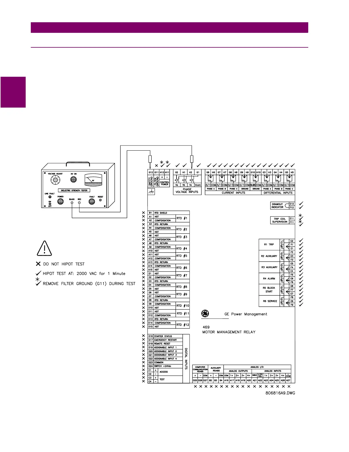
2.2.16 DIELECTRIC STRENGTH TESTING
It may be required to test a complete motor starter for dielectric strength (“flash” or “hipot”) with the 469
installed. The 469 is rated for 2000 V DC isolation between relay contacts, CT inputs, VT inputs, trip coil super-
vision, and the safety ground terminal G12. Some precautions are required to prevent damage to the 469 dur-
ing these tests.
Filter networks and transient protection clamps are used between control power, trip coil supervision, and the
filter ground terminal G11. This is intended to filter out high voltage transients, radio frequency interference
(RFI), and electromagnetic interference (EMI). The filter capacitors and transient suppressors may be dam-
aged by continuous high voltage. Disconnect the filter ground terminal G11 during testing of control power and
trip coil supervision. The CT inputs, VT inputs, and output relays do not require any special precautions. Low
voltage inputs (less than 30 V), RTDs, analog inputs, analog outputs, digital inputs, and RS485 communication
ports are not to be tested for dielectric strength under any circumstance (see below).
Figure 2–24: TESTING THE 469 FOR DIELECTRIC STRENGTH
 Loading...