GE Power Management 469 Motor Management Relay 2-17
2 INSTALLATION 2.2 ELECTRICAL
2
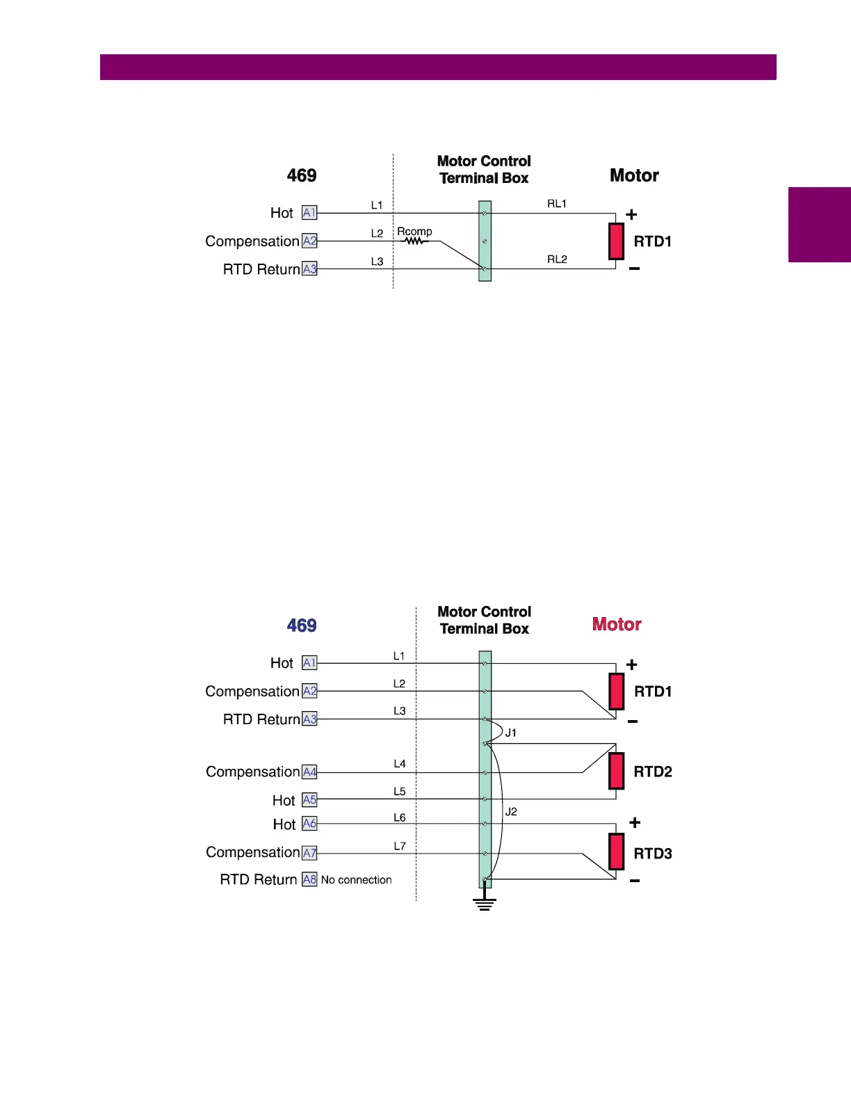
c) TWO WIRE RTD LEAD COMPENSATION
An example of how to add lead compensation to a two wire RTD may is shown in the figure below.
Figure 2–20: 2 WIRE RTD LEAD COMPENSATION
The compensation lead L2 is added to compensate for Hot (L1) and Return (L3), assuming they are all of equal
length and gauge. To compensate for leads RL1 and RL2, a resistor equal to the resistance of RL1 or RL2
could be added to the compensation lead, though in many cases this is unnecessary.
d) GROUNDING OF RTDs
Grounding of one lead of the RTDs is done at either the 469 or at the motor. Grounding should
not
be done in
both places as it could cause a circulating current to flow. Only RTD Return leads may be grounded.
When grounding at the 469, only one Return lead need be grounded as they are hard-wired together internally.
No error is introduced into the RTD reading by grounding in this manner.
If the RTD Return leads are tied together and grounded at the motor, only one RTD Return lead can be run
back to the 469. See the figure below for a wiring example. Running more than one RTD Return lead to the
469 causes significant errors as two or more parallel paths for the return current have been created. Use of this
wiring scheme causes errors in readings equivalent to that in the REDUCED RTD LEAD NUMBER application
described earlier.
Figure 2–21: RTD ALTERNATE GROUNDING
 Loading...