7-8 469 Motor Management Relay GE Power Management
7.2 HARDWARE FUNCTIONAL TESTING 7 TESTING
7
7.2.8 OUTPUT RELAYS
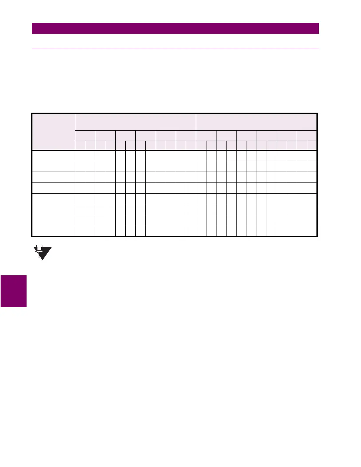
To verify the functionality of the output relays, perform the following steps:
1. Using the setpoint:
S13 TESTING\TEST OUTPUT RELAYS\FORCE OPERATION OF RELAYS: R1 TRIP
select and store values as per the table below, verifying operation
R6 Service relay is failsafe or energized normally, operating R6 causes it to de-energize.
Table 7–13: OUTPUT RELAYS
FORCE
OPERATION
SETPOINT
EXPECTED MEASUREMENT
4
FOR SHORT
ACTUAL MEASUREMENT
4
FOR SHORT
R1 R2 R3 R4 R5 R6 R1 R2 R3 R4 R5 R6
no nc no nc no nc no nc no nc no nc no nc no nc no nc no nc no nc no nc
R1 Trip
4 4 4 4 4 4
R2 Auxiliary
4 4 4 4 4 4
R3 Auxiliary
4 4 4 4 4 4
R4 Alarm
4 4 4 4 4 4
R5 Block Start
4 4 4 4 4 4
R6 Service
4 4 4 4 4 4
All Relays
4 4 4 4 4 4
No Relays
4 4 4 4 4 4
NOTE
 Loading...