GE Power Management 469 Motor Management Relay 4-5
4 SETPOINT PROGRAMMING 4.2 S1 469 SETUP
4
4.2.2 PREFERENCES
Some characteristics can be modified for different situations. Normally this subgroup will not require changes.
•
DEFAULT MESSAGE CYCLE TIME:
If multiple default messages are chosen, the display automatically cycles
through those messages. The display time can be changed to accommodate different user preferences.
•
DEFAULT MESSAGE TIMEOUT:
If no keys are pressed for a period of time then the relay will automatically scan
a programmed set of default messages. This time can be modified to ensure messages remain on the
screen long enough during programming or reading actual values. Once default scanning starts, pressing
any key will return the last message viewed to the screen.
•
AVERAGE MOTOR LOAD CALCULATION PERIOD:
This setpoint adjusts the period of time over which the average
motor load is calculated. The calculation is a sliding window and is ignored during motor starting.
•
TEMPERATURE DISPLAY:
Temperature measurements may be displayed in either Celsius or Fahrenheit.
Each temperature value is displayed as °C or °F. RTD setpoints are always displayed in degrees Celsius.
•
TRACE MEMORY TRIGGER POSITION:
Sets the trigger position for waveform capture. This value represents the
percentage of cycles captured and recorded in the trace memory buffer prior to the trigger (trip).
•
TRACE MEMORY BUFFERS:
Sets the number of traces to capture and the number of cycles for each of the 10
waveforms captured. Note: 10 waveforms are captured for each trace, showing all currents and voltages.
•
DISPLAY UPDATE INTERVAL:
Sets the duration for which the metered current and voltage readings are aver-
aged before being displayed. It does not affect relay protection or function timing in any way. It can be used
to steady the display when readings are bouncing.
•
MOTOR LOAD FILTER INTERVAL:
This value (when non-zero) averages current and PF for the programmed
number of cycles using a running average technique. This setpoint is intended for use on synchronous
motors running at low RPM and driving reciprocating loads. The number of cycles to average can be deter-
mined by using current waveform capture. The number of cycles to complete one stroke can be deter-
mined from this waveform. This value can be used as the starting point for the motor load filter interval.
Additional fine tuning may be required.
WARNING: This averaging may increase trip/alarm times by 16.7 ms for every cycle averaged.
y
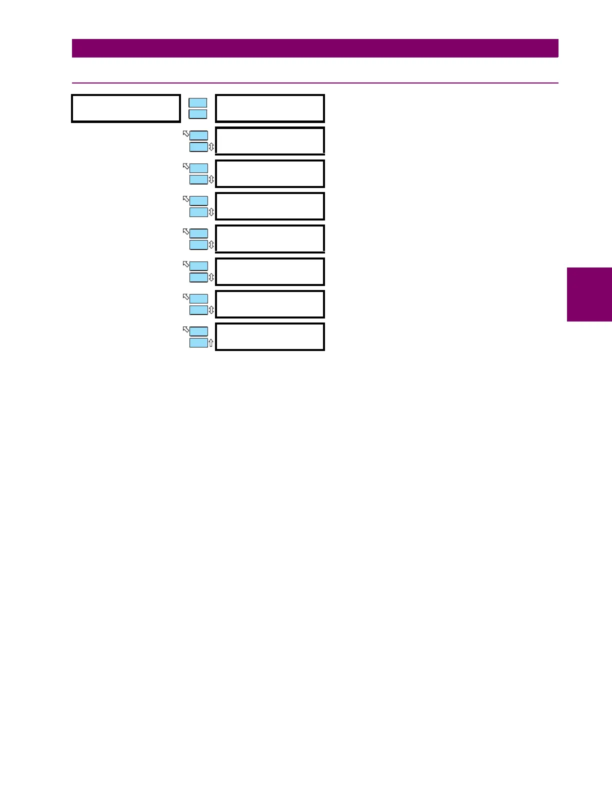
PREFERENCES
y
[ENTER] for more
DEFAULT MESSAGE
CYCLE TIME: 2.0 s
Range: 0.5 to 10.0 sec., step: 1
DEFAULT MESSAGE
TIMEOUT: 300 s
Range: 10 to 900 sec., step: 1
AVERAGE MOTOR LOAD
CALC. PERIOD: 15 min.
Range: 1 to 90 min., step: 1
TEMPERATURE DISPLAY:
Celsius
Range: Celsius, Farenheit
TRACE MEMORY TRIGGER
POSITION: 25%
Range: 1 to 100%, step: 1
TRACE MEMORY BUFFERS
8x14 CYCLES
Range: 1x64, 2x42, 3x32, 4x35, 5x21, 6x18, 7x16, 8x14, 9x12,
10x11, 11x10, 12x9, 13x9, 14x8, 15x8, 16x7
Sets the partitioning of the waveform capture buffer.
DISPLAY UPDATE
INTERVAL: 0.4 s
Range: 0.1 to 60 s, step: 0.1
MOTOR LOAD FILTER
INTERVAL: 0 cycles
Range: 0 to 32 cycles (0 = OFF); step: 1
Note: Setpoint is hidden if frequency set to variable
ENTER
ESCAPE
ð
ð
MESSAGE
ESCAPE
MESSAGE
ESCAPE
MESSAGE
ESCAPE
MESSAGE
ESCAPE
MESSAGE
ESCAPE
MESSAGE
ESCAPE
MESSAGE
ESCAPE
 Loading...