Segment 1 – Module number (default = 0)
Location 5, segment 1 contains the X-10 module number. Program a number from 0-15 to represent
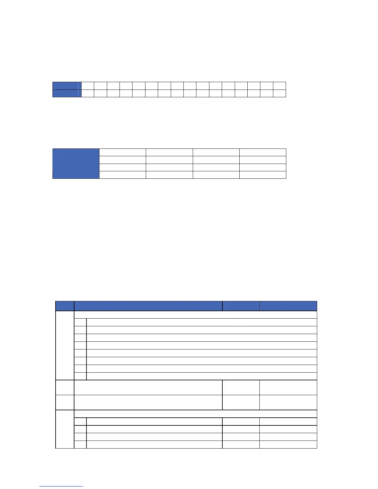
the corresponding X-10 module number from the following table.
Module
1 2 3 4 5 6 7 8 9 10 11 12 13 14 15 16
Segm. 1
0 1 2 3 4 5 6 7 8 9 10 11 12 13 14 15
Segment 2 – House code (default = 0)
Location 5, segment 2 contains the X-10 house code. Program a number 0-15 to represent the
corresponding X-10 house code from the following table.
0 = A 4 = E 8 = I 12 = M
1 = B 5 = F 9 = J 13 = N
2 = C 6 = G 10 = K 14 = O
X-10
ADDRESS
CODES
3 = D 7 = H 11 = L 15 = P
LOCATION 6-13 - PROGRAMMING X-10 ADDRESS FOR OUTPUTS 2-9 (2 segments, numerical
data)
Locations 6 through 13 are used to program the X-10 address for outputs 2-9. Each location has 2
segments. Segment 1 contains the module number and segment 2 contains the house code. Refer to
the instructions in location 5, as well as the charts shown above and the programming worksheets.
NX-534E Programming worksheets
(Defaults are in bold italic text)
LOC DESCRIPTION DEFAULT PROGRAMMING DATA
OPTION FLAGS (Circle numbers to program)
1 OFF: Line hold mode. ON: Call-back mode
2 OFF: Normal two-way. ON: Listen-in only
3 OFF: Automatic speaker lockout. ON: Speaker lockout disabled
4 Microphone A condition at start-up
5 Microphone B condition at start-up
6 ON: Call-in feature answering machine defeat enabled
7 ON: Enable levels 7 & 8
0
8 Reserved
1 CALL-BACK ACCESS CODE
10 = *, 11 = #, 12 = none, 13 thru 15 = any digit
1 2 3 4 5 6
2 LINE HOLD DIGIT
10 = *, 11 = #, 12 = none, 13 thru 15 = any digit
15 (F)
TIMING OPTIONS
1 Line hold timeout (10-255 seconds)
60
2 New trip hang-up time (1-255 seconds)
20
3 Call-back window (1-255 minutes)
5
3
4 Maximum number of digits during code entry (2-255)
12
 Loading...