NX-10 Expander Installation Guide
43
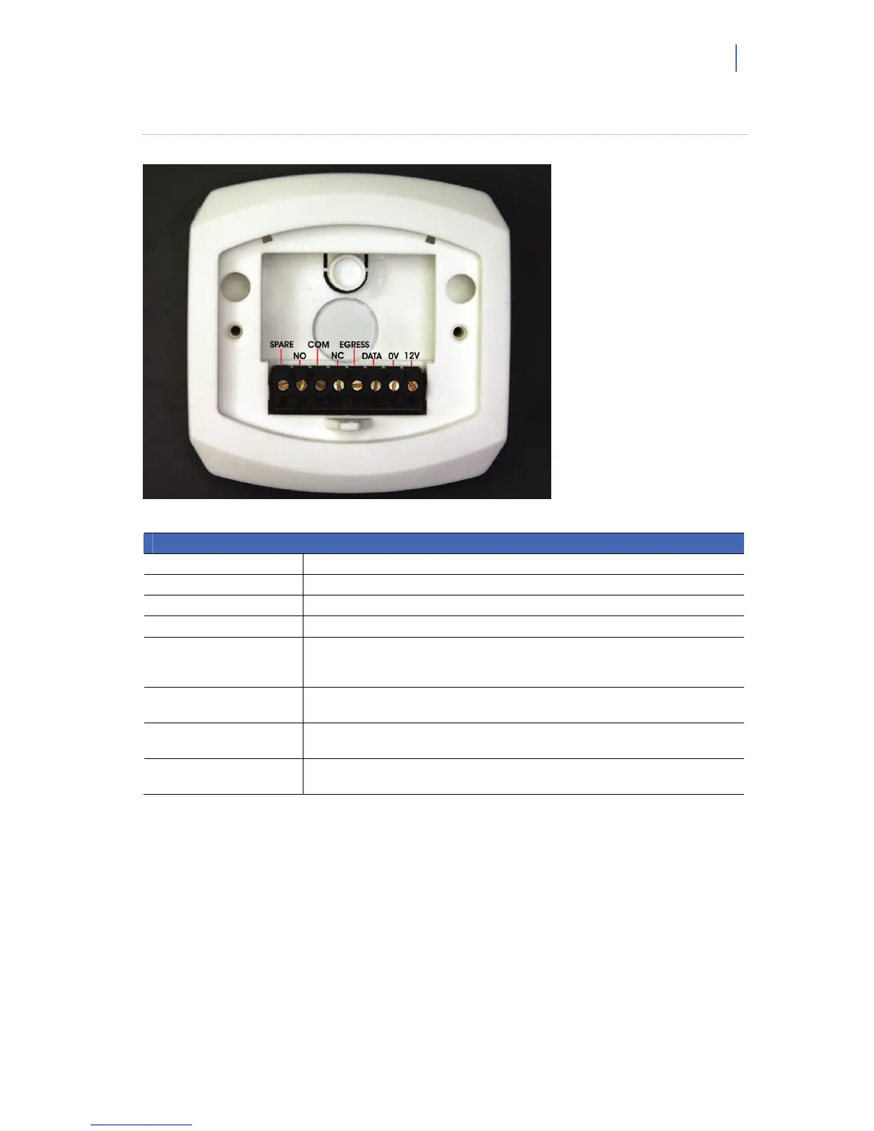
Wiring the NX-1750 ProxPad
Figure 5. Wiring the NX-1750 ProxPad
Terminal Description
1: SPARE Free terminal to connect the panel zone input to a door contact.
2: NO Relay output. The contact is normally open when the relay is not activated.
3: C Relay output. Common contact for the relay.
4: NC Relay output. The contact is normally closed when the relay is not activated.
5: EGRESS
This is an optional EGRESS input. To use this feature, connect the normally open
egress switch between this terminal and COM. If this feature is not used, there is
no need to connect this wire.
6: DATA
Connect to the control panel DATA terminal. This wire is the data signaling
terminal to all the devices on the bus.
7: COM
Connect to the control panel COMMON terminal. This wire supplies the common
side of the power to the ProxPad board.
8: POS
Connect to control panel AUX POWER + terminal. This wire supplies power to the
PROXPAD board.
Notes:
• The terminals of the NX-1750 ProxPad are numbered left to right.
• Egress or RTE: Request To Exit / REX
A condition generated by a device (push button, panic hardware, PIR, switch floor mat, etc.)
that indicates someone is leaving the protected area. No card is required, and no forced door
event is generated. Other names used in the industry for this action are: RTE (Request to Exit),
Egress and Bypass.
 Loading...