Model
5528
A
Fl
atness
Measurement
s
9-6
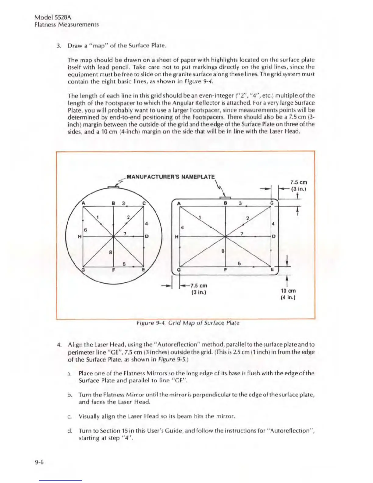
3.
Draw a " map" of the Surface
Plat
e.
The
map
should
be
drawn
on
a sh
eet
of paper with highlights located on
th
e surface plate
itself
with Icad pencil.
Ta
ke care n
ot
to put markings direc
tl
y on
the
grid
lin
es, s
in
ce
th
e
e
quipment
must be
fr
ee
to slide on
th
e granite surface along
th
ese lines. The grid system must
contain
the
eight basic lines,
as
shown
in
Figure 9-4.
The length of
eac
h line
in
this grid should be an cven
-i
nteger ("2", "4", elc.)
mul
tiple of
th
e
length
of
the F
oo
tsp
ace
r to which
the
Angular Rellector is attached.
For
a very large Surface
Pl
ate, you will probably want to use a
la
rger Foolspacer, s
in
ce
measureme
nt
s points
will
be
determined
by
end-Io-e
nd
pos
iti
oning
of
the F
oo
tspacers.
Th
ere shou
ld
also
be
a
7.S
an
(3-
inch) margin between
the
outside of
the
grid and
th
e
edge
of the Sur
fa
ce
Pl
ale on three of the
s
id
es, and a 10 cm (4-
in
ch) margin
on
the side thai
will
be
in
line with the laser Head.
Figure 9-4. G
rid
Map
of
Surface
Plat
e
4. Align the
laser
Head.
usi
ng th
e"
A
ut
oreflection"
method
. parallel to the surfa
ce
plate and to
perimeter line
loGE",
7.5
em (3 inches) oUlside
th
e grid. (
This
is
2.S
em
(1
inch)
in
from the
edge
of
the
Surfa
ce
Pl
ate,
as
shown
in
Figure
9-5
.)
3.
Place one of the Flatness Mirrors so the long
edge
of
it
s base is
flu
sh with
th
e
edgeoft
he
Surface
Plate and parallel
to
line
"G
E".
b. Turn the Flatness
Mi
rror until the mirror is
pe
rpendicular
to
the
edge
of the surface plate,
a
nd
faces
th
e laser Head.
c.
Visual
ly
align the
la
se
r H
ead
so
it
s beam
hil
s the mirror.
d. Turn to Sec
ti
on
1S
in this User's Guide. and follow the
in
structions for "AUloreflection",
starting
al
s
tep
"4",
 Loading...