Mode
l 5528A
Fi
rs
t
look
2
~
16
Po
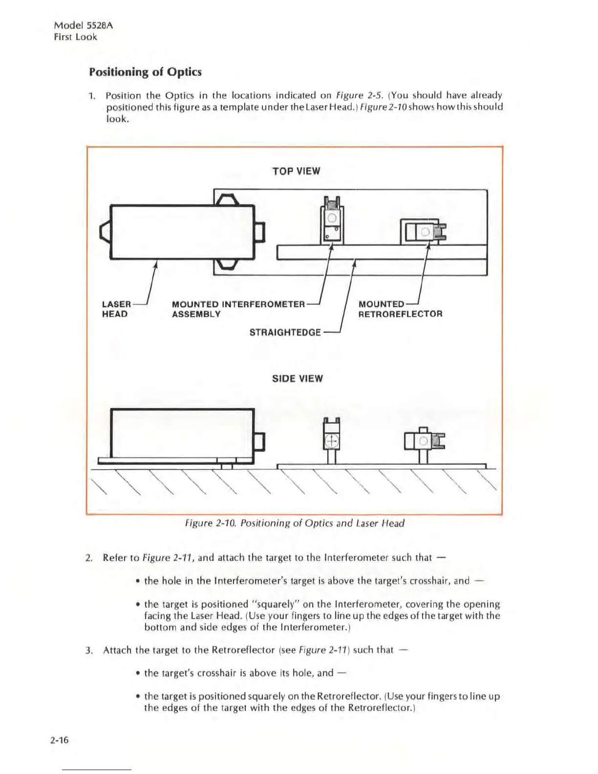
sitioning of Optics
1. Position the Optics in the locations
indi
cated on Figure
2~5.
(You should have already
positioned this
figure
as
a template
under
the laser Head.) Figure2-10shows how this should
l
ook.
TOP
VIEW
Ir\.
!::f
(
~I
.9"
II
I
) i
::I
.....
t
1'-'
t
LASER
MOUNTED
INTERFEROMETER
~
MOUNTEO
-'
HEAD
ASSEMBLY
RETROREFLECTQR
,
--1
STRAIGHTEDGE
SIDE
VIEW
Figure 2-10.
Po
s
i!ioning
of
Optics
.1nd
Laser Head
2.
Refer
to
Figure
2~11,
and al1ach the target to the Interferometer such that -
• the hole in the I
nterfe
rometer's target
is
above the target's
cross
hair, and
• the target is posi
tioned
"squarel
y"
on the I
nterferometer
, covering the
opening
facing the laser Head. (Use
your
fingers to line
up
the edges
of
the target with the
bottom
and side edges
of
the
Interferometer.)
3.
Attach the target
to
the
Retroreflector (
see
Figure 2-11) such that
• the
ta
rget's crosshair
is
above its hole, and -
• the target
is
positioned
squarely on the Retroreflector. (Use your fingers
10
line
up
the edges
of
the larget
with
the edges of the Retroreflec
lor.
)
 Loading...