Interconnection
and
Turn-on
NOTE
Detailed inslructions for step "1" through step
"3"
be
low are
presented in
Sed
ion 5
of
thi
s User's Guide. Do
nol
perform
any
of
these steps until
yo
u
ha
ve
read the related
inf
ormation in
Section
S.
1.
Connect the laser Head and
sen~rs
(
if
yo
u
ha
ve
them) to the Measur
ement
Di
splay.
2.
Ch
eck
the
Measurement
Display's line volta
ge
se
l
ection.
3.
Connect
th
e Measurement Display to
th
e powe r line.
4.
Tu
rn on the system. (The
LINE
sw
itch
is
at
the
lower
left-hand corner
of
the
Me
asu
reme
nt
Disp
l
ay's
front panel, a
nd
tu
rn
s
on
power for both that unit
and
the lase r Head.)
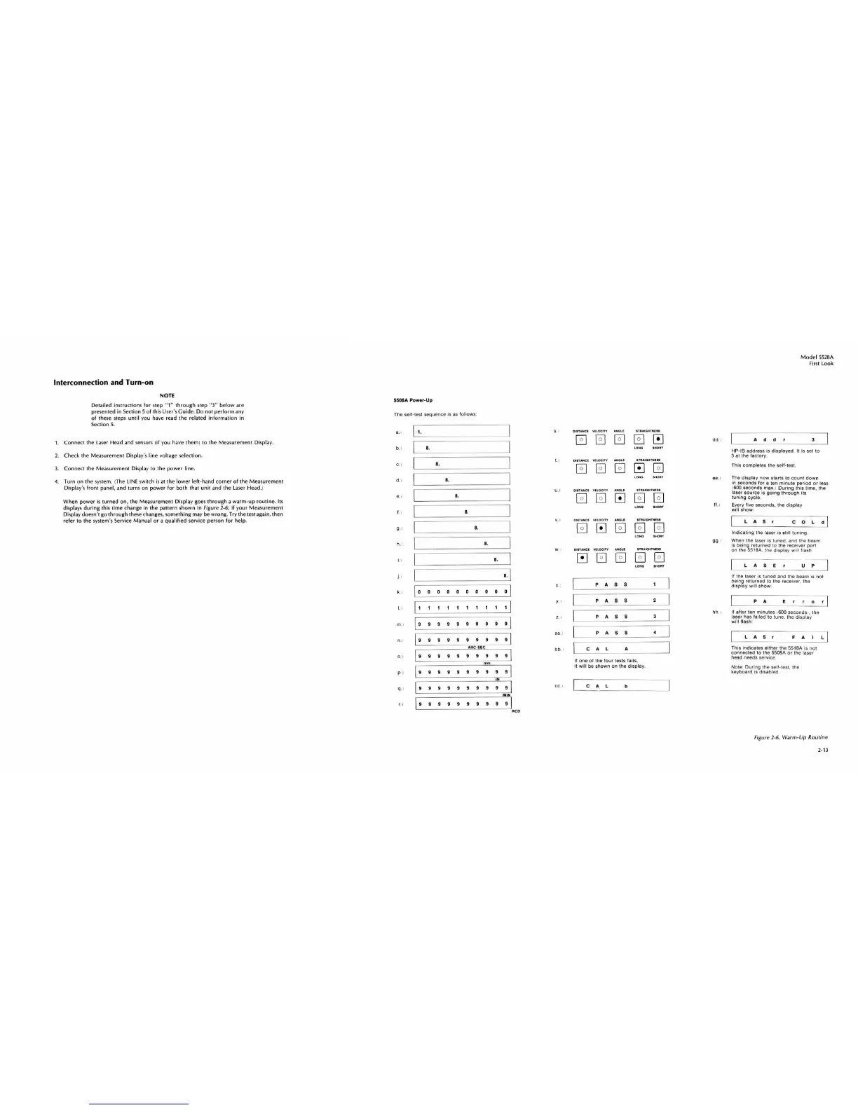
When power
is
turned
on, the Measurement Display goes
through
a
wa
rm-up
routine
.
It
s
displays
during
thiS time chan
ge
in the pattern sh
own
in Figure 2·6;
if
yo
ur
Meas
urement
Display doesn't go
thr
ough th
ese
changes, something may be wrong. Try the test again, then
refer
to
the system's
Se
rvice Manual or a
qualified
service person for hel
p.
550BA
Pow
.r
-Up
The sell-lest sequence is
as
follows
:
a.1
b.i
C.I
dl
.,
1.
1
9
·1
h.1
i.
)
i·
1
k.I
m
.I
O.
I
0 . 1
P I
q. 1
LI
1-1.
I •
I •
I •.
I •
I •
I •
I •
•. I
\ Q 0 0 0 0 0 0 0
o 01
[11111111
[
99999999
•
·1
199
9 9 9 9 9 9
•
9
•
9 9
9 9 9 9 9
IN
I 9 9 9 9 9 9 9 9 9 9 I
IMIN
[ 9 9 9 9 9 9 9 9 9
9[
"-
----------
--
---------------
'CD
s
.•
t.I
U
.I
'
.1
W. I
'.
1
y I
, I
aa
.1
bb
.1
cc
.'
DlUANCI
Vlloc
.n
AN
Oll
lOHO
IHOIIT
QI"ANCl
YUOCln
AN
OLI
ITIIAIOHTNII.
LONO
. H
OII
T
DlIUNCI
YllOCITV
ANOll
I1
I1AIOHTNU.
0B
C!J
LOHO
.HOIIT
OII
UH
CI. YILOClfV
AHGU
.fIIIAIGHT
HI
Il
000
00
lOHO
l
HO
II
T
OI
"AHCI
YllOCITY
AIIOU
LOHO
'HOIIT
PA
S S
1
PAS
S
2
PAS
S
3
PAS
S
4
CAL
A
II
one
01 the
lou
r tests
lai
ls,
it
wi
ll
be
shown
on
t
he
displa
y.
CA
L b
dd
.I
ee
.)
11
.1
9g
·
1
hh. 1
Model
5528A
First l
ook
Add
r 3
HP-IB
address is
displayed
. II
Is
set
to
3 at the
lactor
y.
This
comp
letes
the
self-test.
Tho
disp
l
ay
now
starts to
count
down
In
seconds
l
or
a ten mi
nute
per
iod
or
less
1600
seconds
max. )
During
t
his
tim
e.
the
laser
source
is
going
through
lis
luning
cycle
.
Every
lilla seconds,
the
display
will
show
:
lAS
,
COL
d
In
dicat
i
ng
the laser is Blill
tuning
.
When the
laser
's tuned,
and
t
he
beam
is
be
ing
ret
ufned
10
the
fece
i
ver
port
on
the SStSA. the di
splay
Wi
ll
!lash
L A S E r u p
II t
hO
laser is tuned
and
the
beam
IS
not
being
returned
to
the
receivef,
the
display
will
show
:
P A E
D
,I
If
alter
ten
minu
tes 1600
seconds
I,
the
laser has
la
lled to tune.
the
di
splay
w
ill
flash:
lAS
r
F A I
==;J
Thi
s i
ndicates
either
the
5518A is
not
connec
t
ed
to the 5508A
or
the laser
head needs servi
ce
Note
:
Dur
i
ng
the
sell
-test.
the
keyboard
Is
disab
led
Fi
g
ure
2-6. Warm-Up R
ou
tine
2·
13
 Loading...