Model
5528A
Appendix
A; Prin
cip
les of
Operation
A-6
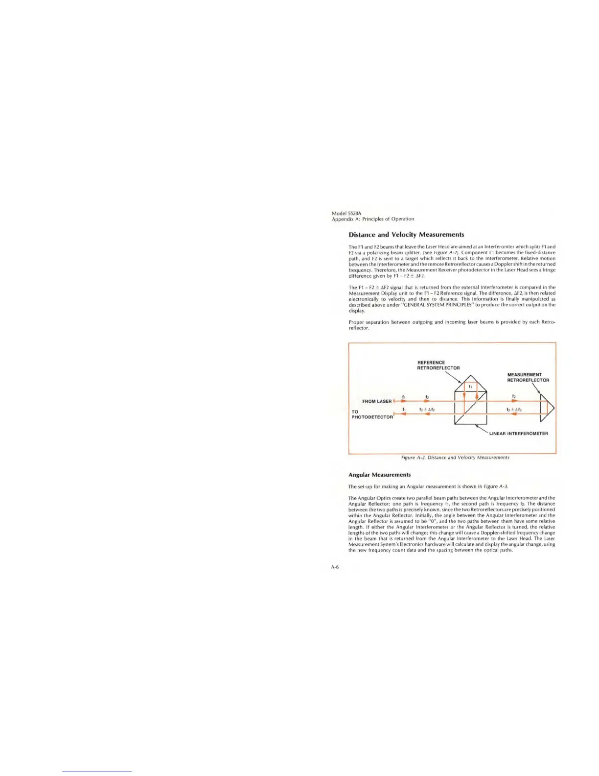
Distance
and
Velocity Measurements
Th
e
F1
and F2 beams that leave
Ih
e laser H
ead
are aimed al
an
Inl
erferomter which
sp
lits
Fl
a
nd
F2 via a
po
larizing beilm spl
itt
cr. (
See
Figure 1\-2).
Compo
nent Fl becomes the
fi
xe
d-distilnce
path, and F2 is
se
nt 10 a larget
which
reflects it back
to
the Inte
rf
erometer
. Relative
motion
between the I
nterferometer
and the
remo
te Retrore
fl
ectorcauses a
Doppler
shift in the returned
frequency.
Th
erefore, the Measureme
nt
Re
cei
ve
r
photode
tect
or
in the l
aser
Head
seeS;1
f
rin
ge
diff
erence given by
fl
-
F2
± aF2.
The
F1
- F2 ± llF2
sig
nal
that
is
returned from th e external
Interf
erometer is compared in the
Measurement Di
sp
la
y unit to the
Fl
-
F2
Reference
sig
na
l.
Th
e difference, dF2,
is
then related
electronically to
ve
locity and then
to
distance. This information
is
finally manipulat
cd
as
described above under
"G
ENERAL
SYSTEM
PR
INCI
PLE
S" to
produ
ce the co
rr
ect ou tput on the
di
sp
la
y.
Proper
se
paration between outgoing and incoming
la
se
r beams is provided
by
eac
h Retro-
reflector.
REFERENCE
RETROAEFlECTOR
MEASUREMENT
/'-
AETROREFlECTOA
/
h
"-
I,
I,
V
I,
"-
FROM LASER
1/
>
TO
I,
f
2
± ~
1
2
'2
i ~
1
2
PH
OTO DETECT
OR
~
LINEAR
INTERFER
O
ME:'
FIgure A-2. D,sfance and Velocity Measuremenls
Angular
Measurement
s
The
se
t-
up
for making
an
Angular measurement
is
shown in Figure 1\-3.
The Angular
Opt
i
cs
creilte
two
para
ll
el beam paths between the Angular Interferometer and the
Angular R
eflecto
r; one
pa
th
is
frequency",
the second path
is
frequen
cy
f2.
The distance
between the t
wo
paths
is
preci
se
ly kn
own,
since the
two
Retrorefieclors are precisely positioned
within
lhe
Angular Reflector. Initially, the angle between the Angular Interferometer and the
Angular R
eflecto
r is
ass
um
ed
to
be
"0",
and the t
wo
paths between them have some relative
length.
If
either
the Angular
Int
erferometer
or
the Angular Reflector
is
turned, the relative
length s of Ihe two paths will change: th
is
change will cause a
Doppler-shilled
frequency change
in the beam
t
ha
t
is
r
et
urn
ed
from
the Angular
Interferom
eter to the L
ase
r Head. The
Laser
Mea
s
ur
ement
Syste
m
's
Elec
tr
oni
cs
hardware wi
ll
ca
lcu late and displ
ay
the angular change, using
the n
ew
frequency co
unt
data and th e spacing between the opt
ica
l path
s.
 Loading...