FC6A S
ERIES
MICROS
MART
U
SER
’
S
M
ANUAL
FC9Y-B1722 2-137
2: P
RODUCT
S
PECIFICATIONS
Communication Modules
The communication modules include the serial communications module that communicate with peripheral devices using RS-232C
or RS-485 communications.
The communication modules are equipped with two serial ports, and RS-232C or RS-485 can be selected and used for each port.
These modules support the maintenance communication function, user communication function, data link communication, and
Modbus communication function.
Use the communication modules by connecting them to the CPU module. For details on the maximum number of communication
modules that can be connected and slots to install those modules, see "Maximum Number of Modules and Slots to Install" on page
2-139. To use a communication module, it must be configured in the Module Configuration Editor. For detailed configuration
methods, see "Module Configuration Editor" on page 12-1. For details on communication settings, see Chapter 3 "Communication
Settings" in the "FC6A Series MICROSmart Communication Manual".
Note: Communication modules cannot be connected to the expansion interface remote slave module.
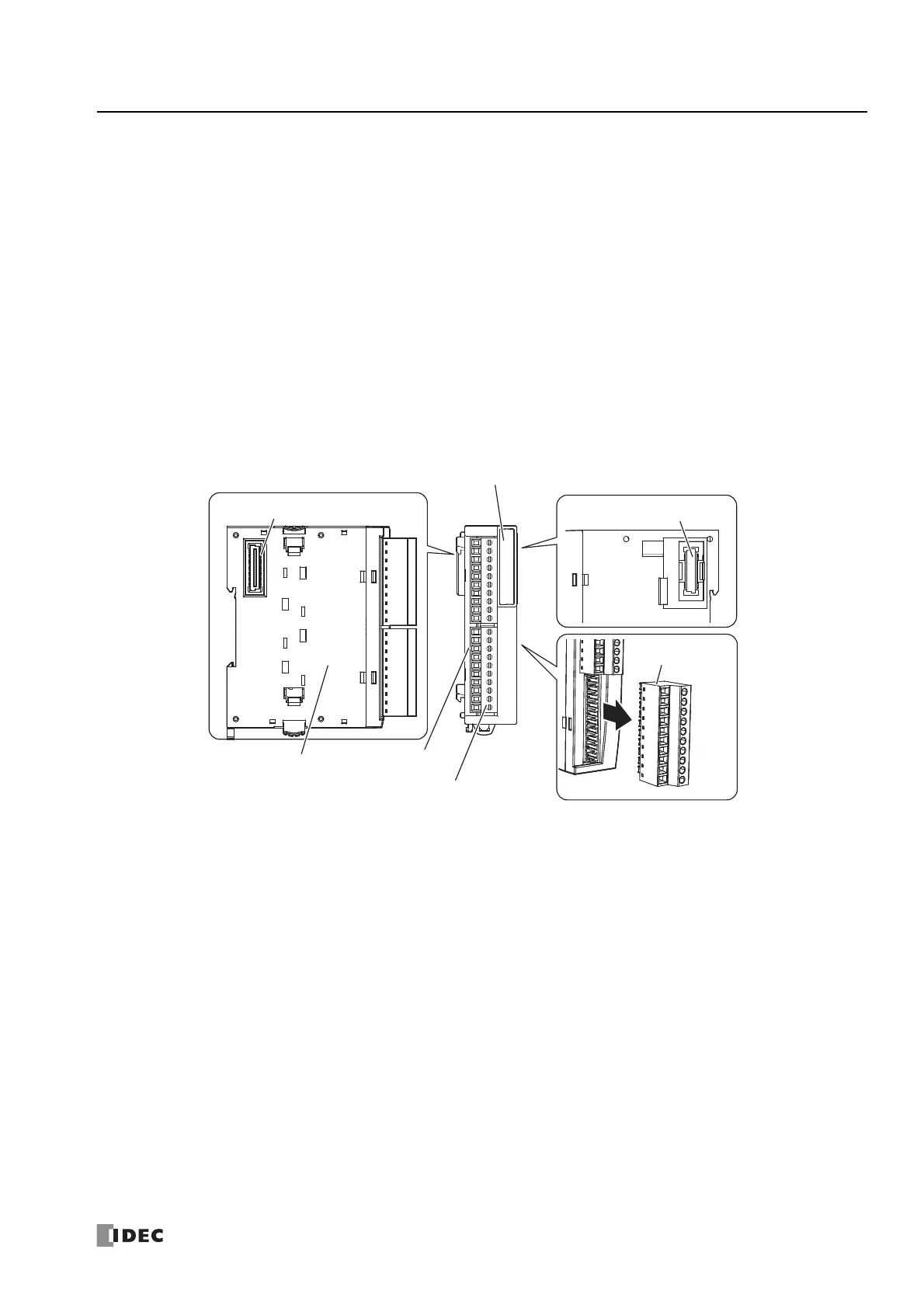
Part Names and Functions
(1) Type Label
Indicates the communication module type number and specifications.
(2) Power LED (PWR)
This LED turns on when the power is supplied to the communication module.
(3) Transmit LEDs (S1, S2)
These LEDs turn on when data is being transmitted from the communication module.
(4) Receive LEDs (R1, R2)
These LEDs turn on when the communication module is receiving data.
(5) Terminal Name Label
Indicates terminal numbers.
(6) Cable Terminals
Wires for RS232C or RS485 communication are connected to these terminals.
(7) Expansion Connector
This connector is used to connect expansion modules and the CPU module.
(7) Expansion Connector
(7) Expansion Connector
(5) Terminal Name
Label
(6) Cable Terminals
(1) Type Label
(6) Cable Terminals
(2) Power LED (PWR)
(3) Transmit LEDs (S1, S2)
(4) Receive LEDs (R1, R2)

 Loading...