3: I
NSTALLATION
AND
W
IRING
3-52 FC6A S
ERIES
MICROS
MART
U
SER
’
S
M
ANUAL
FC9Y-B1722
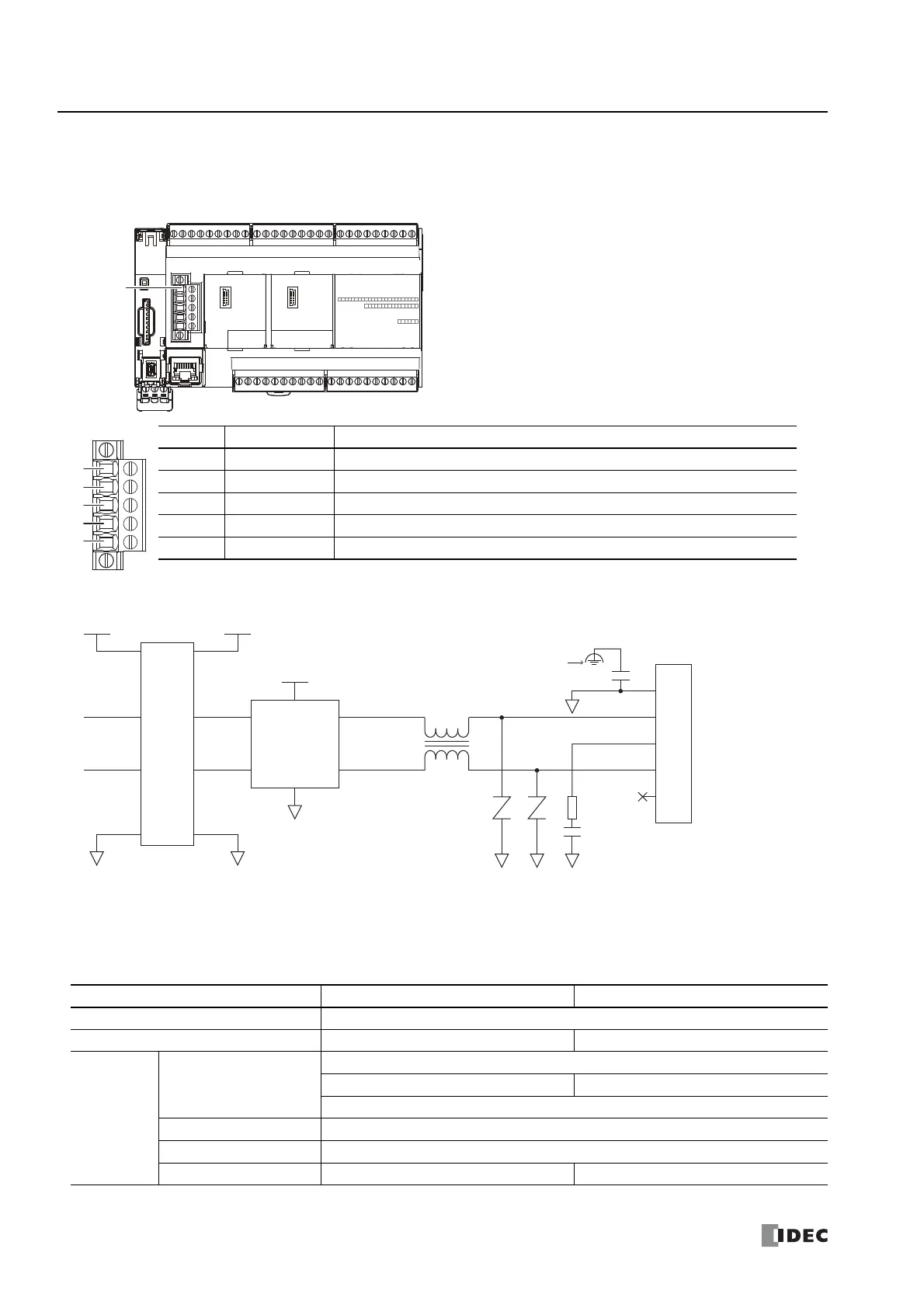
Wiring the CAN J1939 Bus
This section describes the CAN port terminal arrangement, internal equivalent circuit, and specifications.
CAN Port Terminal Arrangement
Internal Equivalent Circuit
CAN J1939 Wiring
The specifications and wiring examples differ according to CAN protocol standard J1939-11 and J1939-15. Connect terminating
resistance (120 Ω, 0.5 W or higher) between CAN_H and CAN_L at both ends of the main line when wiring the CAN port.
No. Signal Wire Details
1 SG CAN external power supply (-)
2 CAN_L CAN_L bus line (dominant low)
3 CAN_SHLD CAN cable shield
*1
4 CAN_H CAN_H bus line (dominant high)
5 (V+) CAN external power supply (+). (N.C. Not connected internally.)
*1 Internally connected to the SG via a resistor and capacitor connected in a series. (R = 1 Ω, 0.68 μF)
CAN Protocol Standard J1939-11 J1939-15
Communication Speed 250 kbps
Nodes 30 10
Cable
Wire Configuration
Twisted pair
Shielded Unshielded
0.3 mm
2
to 0.82 mm
2
(AWG 22 to 18)
Applicable Standards ISO 11898/1993
Characteristic Impedance 120 Ω
Cable Length 40 m maximum, stub 1 m maximum 40 m maximum, stub 3 m maximum
CAN Port
SG
CAN_L
CAN_SHLD
CAN_H
(V+)
SG2
SG2
SG2 SG2 SG2
SG1
SG2
0.68 μF
TXD
RXD
IC
CAN
Transceiver
Terminal Block
(Port 2)
Internally connected to
power supply terminal PE (FE)
VCC1 VCC2
VCC2
1 Ω
Isolated Circuit

 Loading...