FC6A S
ERIES
MICROS
MART
U
SER
’
S
M
ANUAL
FC9Y-B1722 5-13
5: F
UNCTIONS
AND
S
ETTINGS
Memory Backup
The statuses of internal relays and shift register bits are usually cleared at startup. It is also possible to designate all or a block of
consecutive internal relays or shift register bits as “keep” types. Counter current values and data register values are usually
maintained at powerup. It is also possible to designate all or a block of consecutive counters and data registers as “clear” types.
When the FC6A Series MICROSmart is stopped, these statuses and values are maintained. When the FC6A Series MICROSmart is
reset by turning on a designated reset input, these statues and values are cleared despite the settings in the Configure Keep/Clear
Settings dialog box shown below. The keep/clear settings in this dialog box are not maintained when restarting the FC6A Series
MICROSmart.
Since these settings relate to the user program, the user program must be downloaded to the FC6A Series MICROSmart after
changing any of these settings. Device addresses that can be kept or cleared are as follows.
*1 Memory backup for the non-retentive data registers (D70000 to D269999) is not supported.
Programming WindLDR
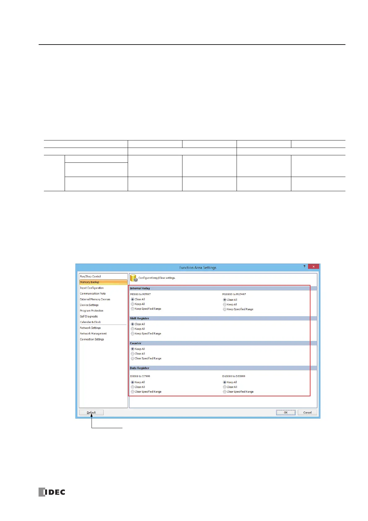
1. From the WindLDR menu bar, select Configuration > Memory Backup.
The Function Area Settings dialog box for Configure Keep/Clear Settings appears.
2. Click the buttons under Internal Relay, Shift Register, Counter, and Data Register to clear all, keep all, or keep/clear specified
range as required.
3. Click OK.
This concludes configuring the settings.
Device Internal Relay Shift Register Counter Data Register
Setting Specify device address to keep Specify device address to clear
Type
All-in-One CPU module
M0000-M7997,
M10000-M17497
R000-R255 C000-C511
D0000-D7999,
D10000-D55999
CAN J1939 All-in-One CPU
module
Plus CPU module
M0000 to M7997,
M10000 to M21247
R000 to R255 C000 to C511
D0000 to D7999,
D10000 to D61999
*1
Resets all Function Area Settings
values to defaults.

 Loading...