3: I
NSTALLATION
AND
W
IRING
3-18 FC6A S
ERIES
MICROS
MART
U
SER
’
S
M
ANUAL
FC9Y-B1722
Input/Output Wiring
This section describes FC6A Series MICROSmart input/output device wiring.
Precautions for I/O Device Wiring
Input Terminal Wiring
When wiring input devices, separate wiring from power, output, and motor lines.
For the wires to use with the CPU modules, expansion modules, and cartridges, see "Recommended Ferrule List" on page 3-46.
*1 24V DC for products with a version number lower than V400. For details on the version number of modules, see "Checking the Version Number"
on page 2-1.
Output Terminal Wiring
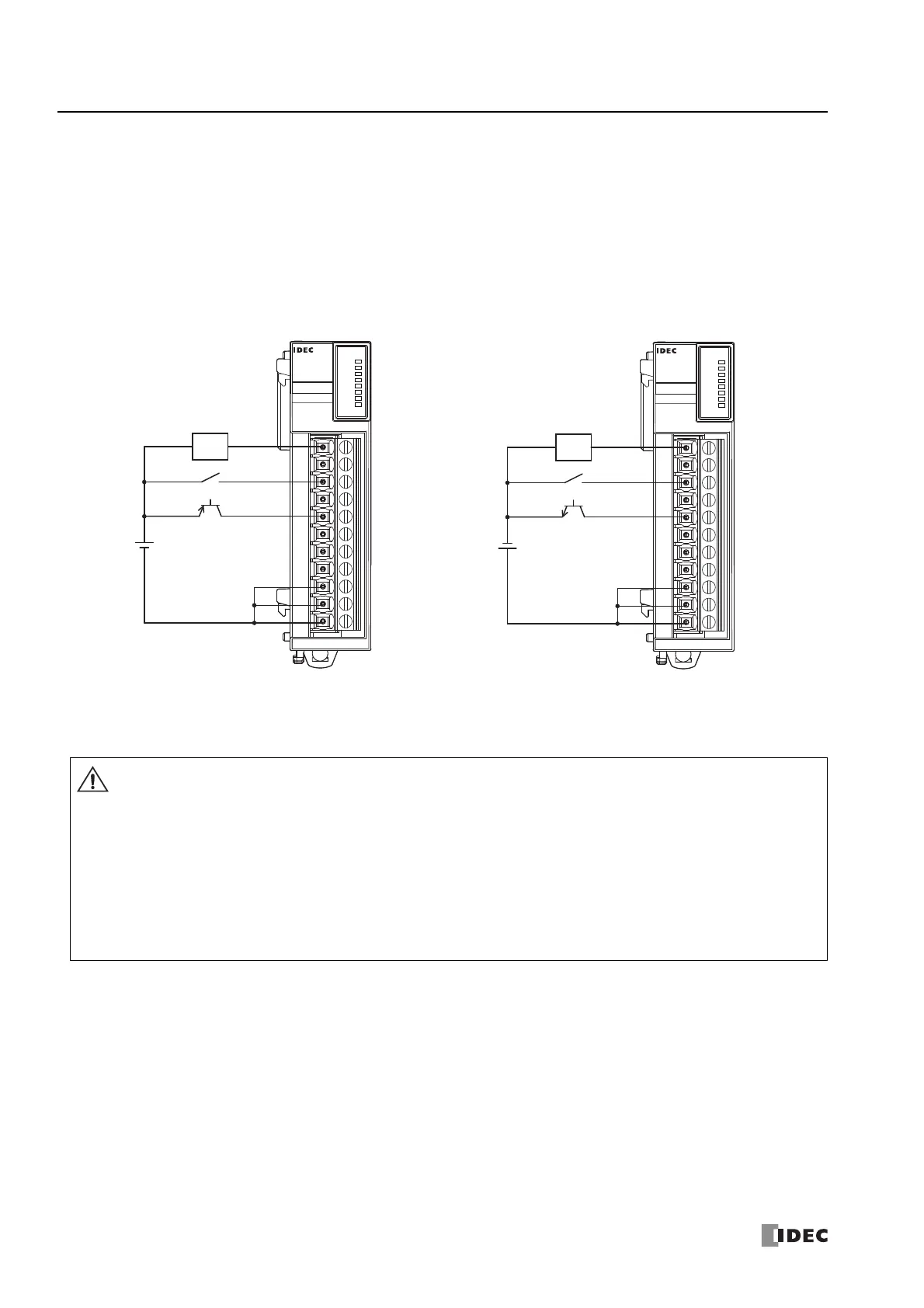
DC Sink Input Wiring Example DC Source Input Wiring Example
DC.IN
0
4
5
6
7
1
2
3
FC6A-N08B1
COM COM COM 7 6 5 4 3 2 1 0
+
-
-
+
PNP
2-wire
Sensor
12/24V DC
*1
DC.IN
0
4
5
6
7
1
2
3
FC6A-N08B1
COM COM COM 7 6 5 4 3 2 1 0
-
+
+
-
NPN
2-wire
Sensor
12/24V DC
*1
If output relays or transistors in the FC6A Series MICROSmart or output modules should fail, outputs may remain on or
off. For output signals which may cause heavy accidents, provide a monitor circuit outside the FC6A Series MICROSmart.
Connect a fuse to the output module, selecting a fuse appropriate for the load.
When equipment containing the FC6A Series MICROSmart is intended for use in European countries, insert an IEC 60127-
approved fuse to each output of every module for protection against overload or short-circuit. This is required when
equipment containing the FC6A Series MICROSmart is destined for Europe.
When driving an inductive load that emits noise like a magnet or a valve, to reduce noise and protect circuits, use a diode
for the output on DC power type models and a surge absorber for the output on AC power type models.
For the wires to use with the CPU modules, expansion modules, and cartridges, see "Recommended Ferrule List" on page
3-46.
Caution

 Loading...