13: T
ROUBLESHOOTING
13-10 FC6A S
ERIES
MICROS
MART
U
SER
’
S
M
ANUAL
FC9Y-B1722
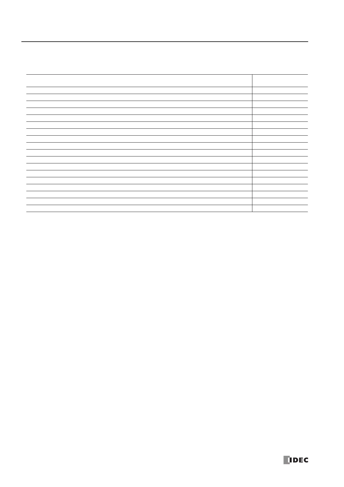
Troubleshooting Diagrams
When one of the following problems is encountered, see the following trouble shooting diagrams:
Problem
Troubleshooting
Diagram
The power is not on. Diagram 1
Operation has not started. Diagram 2
An error has occurred. Diagram 3
Input does not operate normally. Diagram 4
Output does not operate normally. Diagram 5
Cannot stop or reset operation. Diagram 6
Watchdog timer error occurs and the CPU does not run. Diagram 7
The interrupt/catch input cannot receive short pulses. Diagram 8
Frequency measurement does not work. Diagram 9
Data is not transmitted at all in the user communication mode. Diagram 10
Data is not transmitted correctly in the user communication mode. Diagram 11
Data is not received at all in the user communication mode. Diagram 12
Data is not received correctly in the user communication mode. Diagram 13
Modbus master communication does not work. Diagram 14
Long communication cycle for Modbus RTU master communication or Modbus TCP client communication. Diagram 15
WindLDR and the FC6A Series MICROSmart cannot communicate. Diagram 16
WindLDR does not communicate with PLC via USB. Diagram 17
Modbus master communication request is slow. Diagram 18

 Loading...