5: F
UNCTIONS
AND
S
ETTINGS
5-44 FC6A S
ERIES
MICROS
MART
U
SER
’
S
M
ANUAL
FC9Y-B1722
Analog Voltage Input
The section describes the analog input built into the FC6A Series MICROSmart.
Function Description
The FC6A Series MICROSmart is equipped with a built-in analog voltage input function. This function acquires 0 to 10V DC voltage
analog input by converting it to a digital value. The converted analog signal is stored in a special data register. Only one analog
input can be used.
Analog input value storage location
The converted analog signal is stored in a special data register (D8058: read-only) as a digital value. This digital value is updated with
each scan. The range of the value that is stored in the special data register (D8058: read-only) can be specified with the data type.
Analog input status (D8060)
The analog input status code is stored in special data register D8060 (analog input status).
Analog Input Filter
The analog input data is averaged by the specified filter count. This can reduce rapid fluctuations in analog input.
The larger this value is set, the slower the tracking of the change in analog input becomes.
When filtering, the input value is calculated with the equation below.
Analog input data types
The range of analog values that can be handled with the specified data types are as follows.
Status code Details Analog Input Value
0 Normal operation Current analog input value
1
Converting data
(occurs only once during the initial conversion when the power is turned on)
Undefined
2 Initializing 0
5
Wiring fault (out of maximum range)
When the analog input value exceeds 11 V
Upper limit value
3, 4, 6 to 65,535 Reserved —
Count Details
1 to 255 The input value is set as the average value of n samples of analog input data. (n: Count)
Details
Data type All-in-One CPU Module Plus CPU Module
Binary data 0 to 1,000 0 to 4,000
Optional range
Minimum to maximum
(The minimum and maximum in a range between 0 to
1,000 where minimum ≤ maximum)
Minimum to maximum
(The minimum and maximum in a range between -32,768
to 32,767 where minimum ≤ maximum)
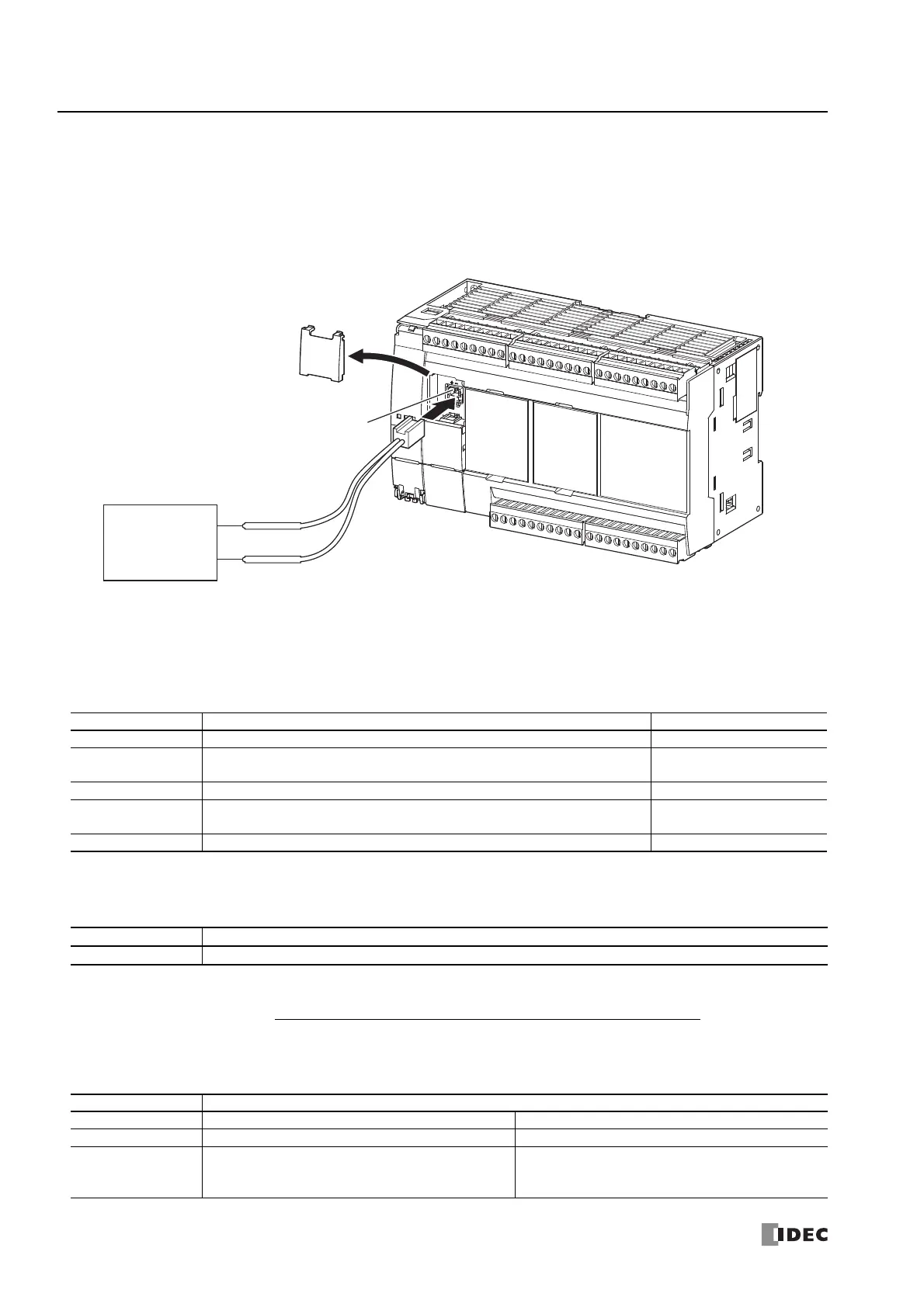
+ (Red)
– (Black)
External Device
(Voltage Input)
Analog Input
Analog input value after filtering =
Total analog input values for filter count (n) worth of scans
Filter count n

 Loading...