3: I
NSTALLATION
AND
W
IRING
3-24 FC6A S
ERIES
MICROS
MART
U
SER
’
S
M
ANUAL
FC9Y-B1722
Using the Ports
This section describes how to use the analog input and analog potentiometer, serial port 1, Ethernet port 1, and the USB port.
Removing and Attaching the Analog Port Cover
The following procedure describes how to remove and attach the analog port cover.
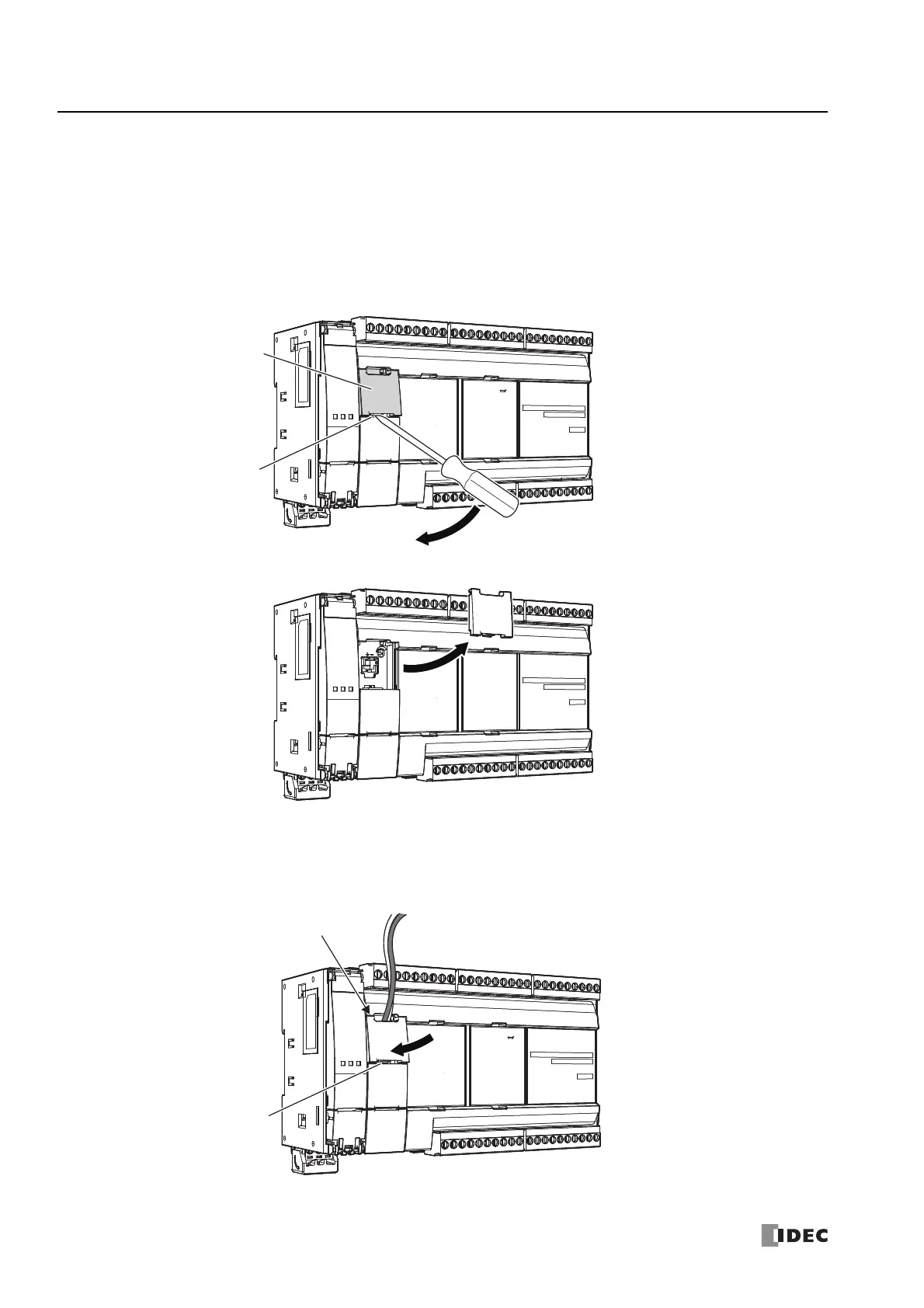
Removing the Analog Port Cover
1. Insert a flathead screwdriver into the screwdriver slot on the analog port cover and slowly move the screwdriver in the
direction of the arrow to unlock the bottom lock.
2. Lift up the analog port cover in the direction of the arrow to remove it.
Attaching the Analog Port Cover
Attach the analog port cover after wiring the port.
1. Insert the tabs at the top of the analog port cover into the analog port cover slots, then push the bottom of the analog port
cover in the direction of the arrow to attach it.
Note: Take care with the orientation of the analog port cover. The groove to insert the screwdriver goes on the bottom.
Analog Port Cover
Screwdriver Slot
Insert the tabs at the top
of the analog port cover
Screwdriver Slot Groove

 Loading...