5: F
UNCTIONS
AND
S
ETTINGS
5-42 FC6A S
ERIES
MICROS
MART
U
SER
’
S
M
ANUAL
FC9Y-B1722
Input Filter
The input filter function is used to reject input noises. The catch input function described in the preceding section is used to read
short input pulses to special internal relays. To the contrary, the input filter rejects short input pulses when the FC6A Series
MICROSmart is used with input signals containing noises.
Different input filter values can be selected for inputs I0 through I27 in four groups using the Function Area Settings. Selectable
input filter values to pass input signals are 0 ms, and 3 through 15 ms in 1 ms increments. Default value is 3 ms for all inputs I0
through I27. Input I30 and above on all expansion input modules have a fixed filter of 3 ms. The input filter rejects inputs shorter
than the selected input filter value minus 2 ms.
Normal inputs require a pulse width of the filter value plus one scan time to receive input signals. When using the input filter
function, select Normal Input under Special Inputs on the Input Configuration dialog box in the Function Area Settings.
Since these settings relate to the user program, the user program must be downloaded to the FC6A Series MICROSmart after
changing any of these settings.
Programming WindLDR
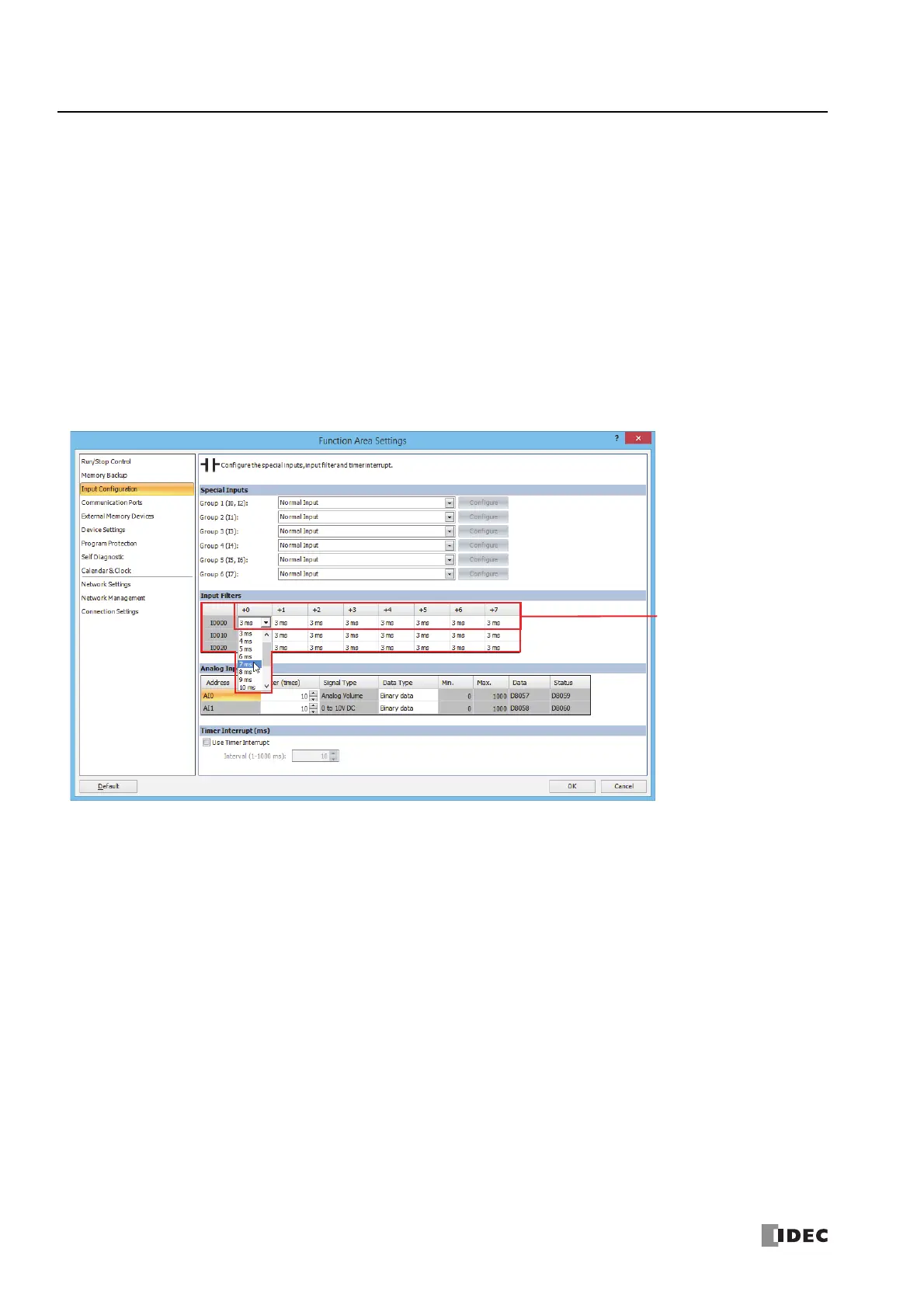
1. From the WindLDR menu bar, select Configuration > Input Configuration.
The Function Area Settings dialog box for Input Configuration appears.
2. Select an input filter value for each group of inputs.
Input Filter Values and Input Operation
Depending on the selected values, the input filter has three response areas to reject or pass input signals.
Reject area:
Indefinite area:
Pass area:
Input signals do not pass the filter (selected filter value minus 2 ms).
Input signals may be rejected or passed.
Input signals pass the filter (selected filter value).
The columns displayed next to I0
indicate I0 to I7.

 Loading...