FC6A S
ERIES
MICROS
MART
U
SER
’
S
M
ANUAL
FC9Y-B1722 1-17
1: G
ENERAL
I
NFORMATION
Ethernet Communication
The FC6A Series MICROSmart can be connected to the Ethernet network using Ethernet port 1 and communicate with network
devices over Ethernet.
The All-in-One CPU module and CAN J1939 All-in-One CPU module have eight TCP/IP connections and the Plus CPU module has 16
TCP/IP connections that can be used for Ethernet communication. Different communication protocols can be simultaneously used
on these connections. Each connection can be configured for maintenance communication server, user communication server/
client, or Modbus TCP server/client communication.
Supported ports
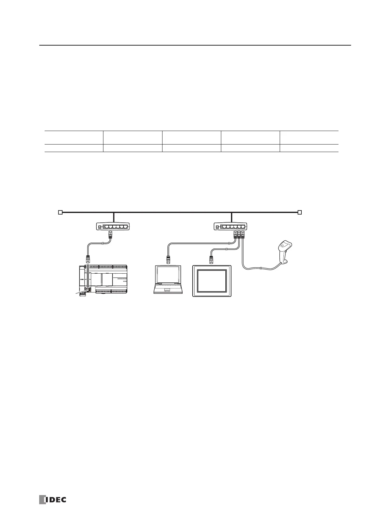
■ Ethernet Communication Example
This example shows Ethernet communication between the FC6A Series MICROSmart equipped with Ethernet port 1, an operator
interface, and a computer. Among the three connections the FC6A Series MICROSmart has, Connection
1 is configured as
maintenance communication server for the computer to communicate with the FC6A Series MICROSmart. Connection 2 is
configured as Modbus TCP server for the operator interface to communicate with the FC6A Series MICROSmart. Connection 3
communicates with the barcode reader with the user communication. Connection 4 to connection 8 are not used.
Notes:
When accessing the FC6A Series MICROSmart over the Internet, adequate security measures for the network to prevent unauthorized access
are required. Be sure to consult your network administrator or Internet service provider. IDEC bears no responsibility for damages or
problems caused due to security in Ethernet communication.
Restrict the access to FC6A Series MICROSmart with IP addresses and ports by using appropriate measures such as the firewall.
USB Port Serial Port 1 Ethernet Port 1 and 2
Communication
Cartridge
CAN Port
No No Yes No No
Ethernet Port 1
Operator Interface
Windows Computer
FC6A Series MICROSmart
Ethernet Hub Ethernet Hub
Ethernet
Barcode Reader

 Loading...