FC6A S
ERIES
MICROS
MART
U
SER
’
S
M
ANUAL
FC9Y-B1722 2-143
2: P
RODUCT
S
PECIFICATIONS
Expansion Interface Modules
The expansion interface modules are available as an expander that is added in between expansion modules to expand the number of
connected modules and as remote modules (remote master and remote slave) that are daisy chained by Ethernet cables and allow
expansion modules to be positioned away from the CPU module. Remote master/slave modules can be connected only to the Plus
CPU module.
Expansion Interface Module (Expander)
The number of expansion modules that can be connected to the CPU module (basic expansion side) is seven modules, but
additional eight expansion modules (expansion interface side, maximum 256 I/O points) can be connected by installing the
expansion interface module (expander).
Notes:
Only one expansion interface module (expander) can be connected to one CPU module.
When using the expansion interface module (expander) together with expansion interface modules (remote master/slave) on the Plus CPU
module, one expansion interface module (expander) can be connected per remote slave that is daisy chained to the remote master. For
details, see "Expansion Interface Modules (Remote Master/Slave)" on page 2-146.
The maximum number of modules that can be connected depends on the modules. For detailed restrictions when using the expansion
interface module and connection examples, see "Connection Restrictions When Expanding the PLC" on page 3-37.
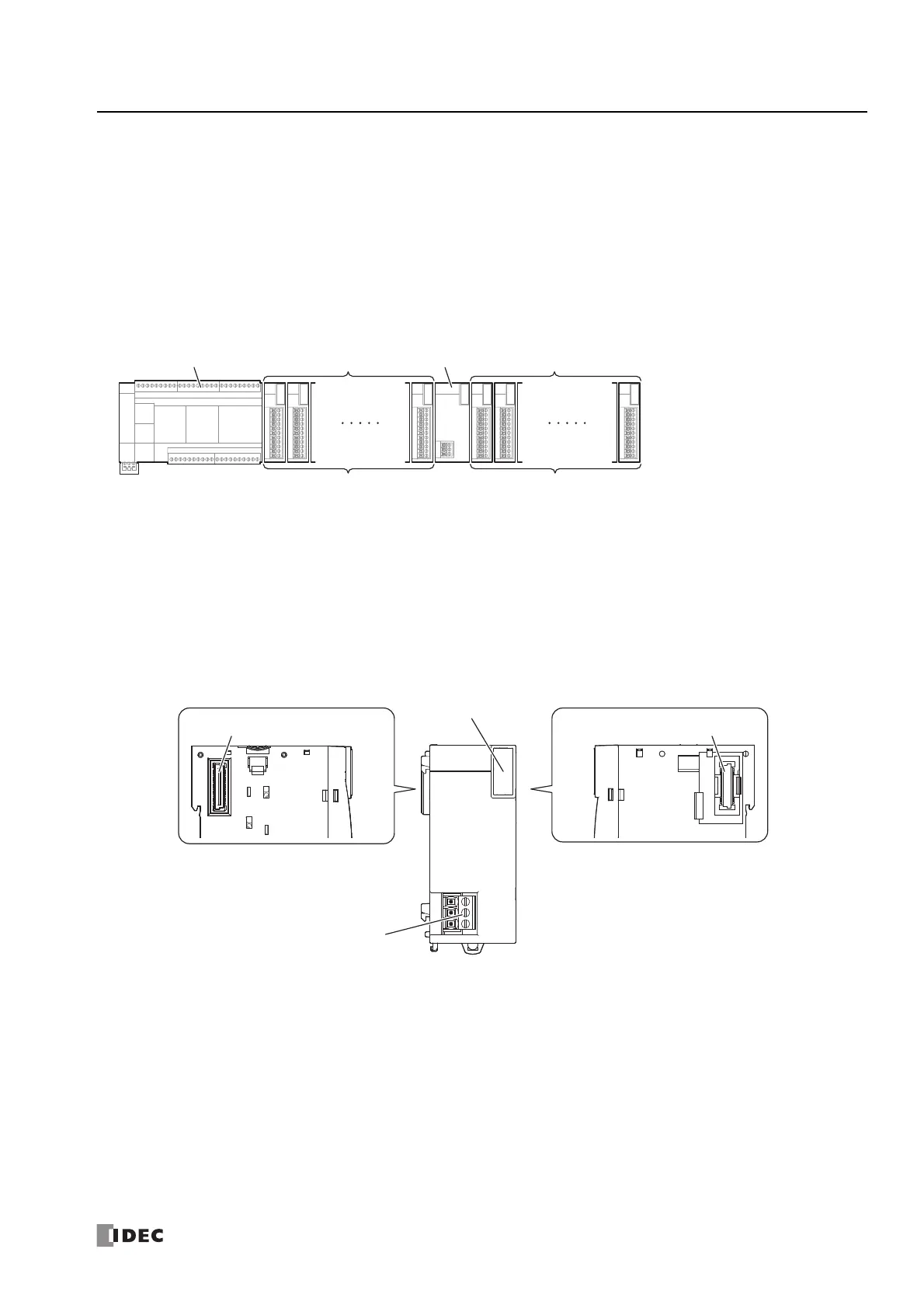
Parts Description
FC6A-EXM2
(1) Power LED [PWR]
This LED turns on when the power is supplied to the expansion interface module (expander).
(2) Expansion Connector 1
This connector is used to connect the expansion module on the basic expansion side.
(3) Expansion Connector 2
This connector is used to connect the expansion module on the expansion interface side.
(4) Power Terminal Block
These terminals supply 24V DC power to the expansion interface module (expander).
Expansion ModulesCPU Module
Expansion Interface Module (Expander)
(FC6A-EXM2, FC6A-EXM24)
Expansion Modules
Basic Expansion Side
7 maximum 8 maximum
Expansion Interface Side
(4) Power Terminal Block
(1) Power LED [PWR]
(2) Expansion Connector 1 (3) Expansion Connector 2

 Loading...