EN
EN-14 80447162 Rev B
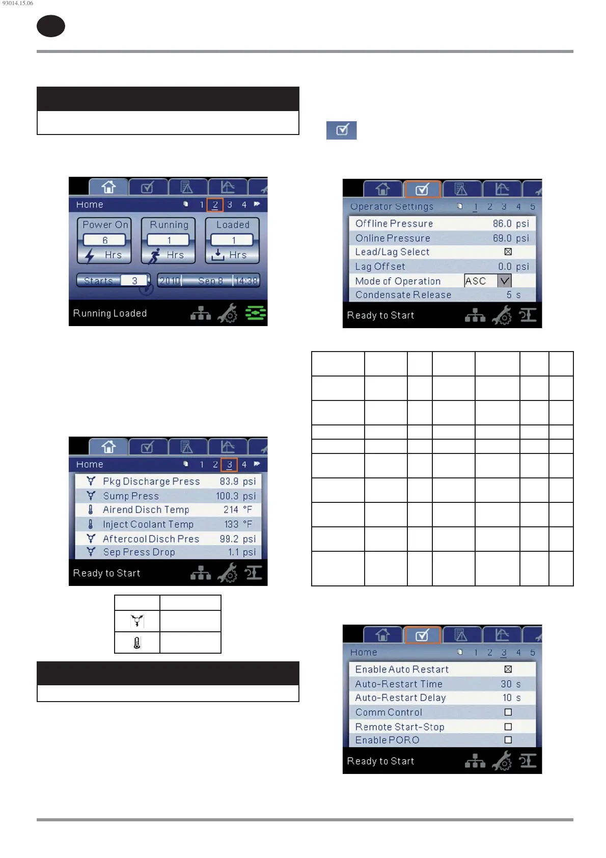
Run Hours indicate the number of hours the compressor has been
running.
NOTICE
The online and o ine set points can be selected and modi ed on this
page. All other information on this page is read only.
Page 2 : Counters
Figure 12 : Counters
Hour Meters indicate the hours that: the controller has been powered
up, the compressor has been running, and the compressor has running
loaded.
Starts indicate the number of times a start is attempted on the
compressor.
Date & Time is adjustable and con gurable in the General Settings folder.
Pages 3-4: Analog Inputs
Figure 13 : Analog Inputs
Icon Meaning
Pressure
Temperature
NOTICE
All information on these pages is read only.
The following inputs are displayed in this section:
Package Discharge Pressure
Sump Pressure
Airend Discharge Temperature
Injected Coolant Temperature
After-cooler Discharge Temperature
Separator Pressure Drop
•
•
•
•
•
•
•
•
•
•
Coolant Filter Pressure Drop
Inlet Vacuum
After-cooler Discharge Pressure (integrated dryer compressors only)
Remote Pressure (optional)
Operator settings folder
Pages 1-2: Operator Settings
Figure 14 : Operator Settings
Table 10 : Operator Settings
Operator
Settings
Selection Min. Max. Default Step Unit
O ine
Pressure
--- 75 Rated+10 Rated+10 1 psi
Online
Pressure
--- 65 O ine-10 O ine-10 1 psi
Lead/Lag Lead/Lag --- --- Lead --- ---
Lag O set --- 0 45 0 1 psi
Mode of
Operation
Mode --- --- ON/OFF
line
--- ---
Condensate
Release
--- 2 20 5 1 sec
Condensate
Interval
--- 90 270 180 1 sec
Stop Delay
Time
--- 10 30 10 1 sec
Star-Delta
Time / Start
Time
--- 5 30 10 1 sec
Pages 3-5: Operator Options
Figure 15 : Operator Options
•
•
•
•
93014.15.06
 Loading...