EN
EN-20 80447162 Rev B
Table 15 : Backlight Settings
Display Text Description
Backlight
Brightness
Adjusts the brightness of the display.
Enable Backlight
Auto-O
Enables the controller to shut-o the backlight if
there is no user activity for the delay time shown.
Backlight Auto-O
Delay Time
Determines how many seconds of inactivity it will
take before the controller will shut-o the backlight.
NOTICE
The backlight will be switched ON whenever any of the controller’s
keys are pressed.
The START, STOP, LOAD, UNLOAD, RESET, and ACKNOWLEDGE keys on
the controller remain functional while the backlight is switched OFF. It
is recommended to press the ENTER key or one of the navigation keys
in order to switch the backlight ON.
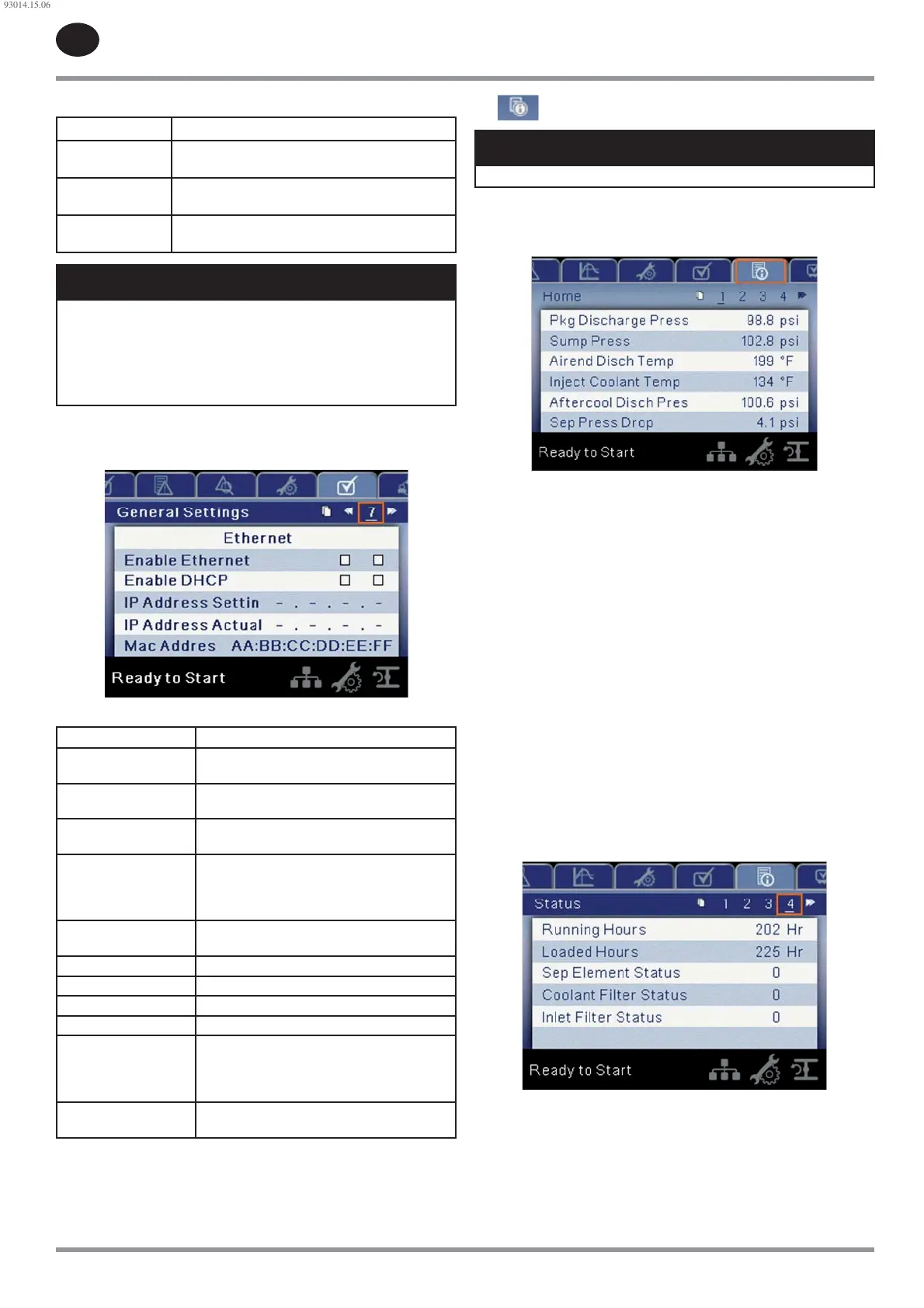
Pages 7-8: Ethernet Settings
Figure 28 : Ethernet Settings
Table 16 : Ethernet Settings
Display Text Description
Enable Ethernet Allow connection by users to utilize the
network enabled functionality of the controller
Enable DHCP Allow the controller to automatically receive an
IP address from the Local Area Network (LAN)
IP Address Setting When DHCP is not enabled, this setpoint sets
the IP address of the controller.
IP Address Actual This will match the IP address setting when
DHCP is not enabled. If DHCP is enabled
this will display the address assigned to the
controller by the DHCP server.
MAC Address This is the unique hardware MAC address for
the controller. This can not be changed.
Subnet Mask Setting Setpoint for the subnet mask
Subnet Mask Actual Current reading/setting for the subnet mask
Default Gateway Setting Setpoint for the default gateway.
Default Gateway Actual Current reading/setting for the default gateway.
Accept After editing the desired setpoint navigate
to the accept setting and press enter in order
for the values in the setting variables to be
con rmed by the controller.
Cancel Discard any changes made to the Ethernet
settings.
Status folder
NOTICE
All information on these pages is read only.
Pages 1-3: Analog Inputs
Figure 29 : Analog Inputs
The following inputs are displayed in this section:
Package Discharge Pressure
Sump Pressure
Airend Discharge Temperature
Injected Coolant Temperature
After-cooler Discharge Temperature
Separator Pressure Drop
Coolant Filter Pressure Drop
Inlet Vacuum
After-cooler Discharge Pressure (integrated dryer compressors only)
Remote Pressure (optional)
Coolant Filter Inlet Pressure
Coolant Filter Outlet Pressure
Interstage Pressure (2-stage compressors only)
Evaporator
Condenser
Page 4: Compressor Data
Figure 30 : Compressor Data
The following data are displayed in this section:
Power ON Hours
Running Hours
Loaded Hours
Real Time Clock
•
•
•
•
•
•
•
•
•
•
•
•
•
•
•
•
•
•
•
93014.15.06
 Loading...