80447162 Rev B EN-5
EN
General Electrical
A quali ed electrician shall perform all electrical installations and service.
The compressor shall be properly grounded / earthed in compliance with all
applicable standards and regulations (local, state, country, federal, etc.).
Installation of this compressor shall be in compliance with all applicable
standards and regulations (local, state, country, federal, etc.).
The compressor shall have its own isolator situated adjacent to it. The fuse
protecting the circuit and the compressor shall be selected in accordance
with recognized code requirements on the basis of the data provided in the
speci cation sheet.
Feeder cables shall be sized to ensure that the circuit is balanced and not
overloaded by other electrical equipment. The length of wiring from a
suitable electrical feed point is critical as voltage drops may impair the
performance of the compressor.
NOTICE
For VSD, cable sizes may vary considerably so the line reactor is
equipped with copper bus connections. These connections can accept
bolts between 6 mm and 12 mm.
Feeder cable connections to incoming terminals L1-L2-L3 shall be tight and
clean.
The applied voltage shall be compatible with the compressor data plate
ratings.
The control circuit transformer has di erent voltage tappings. Ensure that
these are set for the speci c applied voltage prior to starting.
Remove the blind plate to cut a hole for incoming power connection. If it
is necessary to make a hole in the control box in a di erent location, care
should be taken to not allow metal shavings to enter the starter and other
electrical components within the box. If another hole is used, the original
hole shall be blocked o .
The feeder cable shall be suitably glanded in to the starter box to maintain
proper ingress protection. Fixed speed starter boxes are rated for NEMA 4
/IP65, and variable speed drive starter boxes are rated for NEMA 12/IP54.
For variable speed drive starter boxes, the feeder cable shall be glanded to
ensure that dirty air does not by-pass the lters.
On completion of electrical installation, check that the blower or fan motor
rotation is correct.
Variable speed drive compressors are designed for use, where the electricity
supply is separated from nearby residential and commercial areas. If the
compressor is to be used in a light industrial, residential or commercial
environment where the local supply network is shared, further Radio
Frequency (RF) screening measures may be required. Consult your local
distributor/supplier for details of the optional RF lter.
Variable speed drive compressors have an anti-condensation heater
and thermostat in the electrical box. This circuit can be connected to
an independent electrical supply of either 110 V or 230 V single phase,
dependent on the country of installation. The supply shall be suitably fused
and an independent isolator installed adjacent to the compressor. Verify that
the thermostat is adjusted to 29 ˚C (85 ˚F). This shall be done in accordance
with recognized codes. It is good practice, and sometimes mandatory,
to display suitable signs warning that the compressor has two separate
electrical supplies which both shall be isolated before any work is attempted.
For Variable speed drive compressors, the heater circuit can also be supplied
from the 110 V tapping of the control transformer and connected as shown
on the schematic wiring diagram furnished separately from this manual.
NOTICE
Main and fan motor insulation shall be tested by a quali ed electrician
prior to initial start-up or following an extended shutdown period in
cold and damp conditions.
Special Electrical Considerations for Variable Speed
Drive (VSD) Compressors
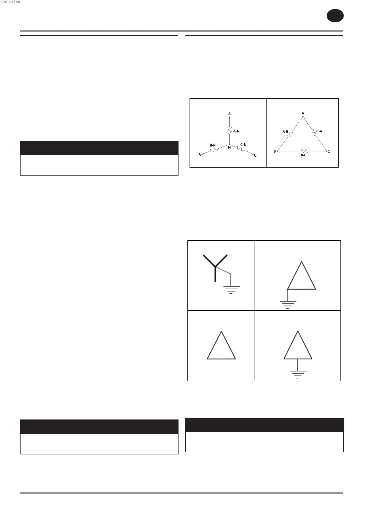
Primary Input Power Supply
The primary input power for the compressor can come from di erent
transformer sources and con gurations. The most typical sources and
con gurations are a wye secondary and a delta secondary.
Figure 2 : Wye and Delta Con gurations
Wye
Delta
How to Ground
In most conditions, you must ground a wye system. Refer to local electrical
codes. When you ground a wye system, the voltage to ground becomes
stable and controlled. This prevents a system from damage by conditions that
cause high voltage to ground. It is typical to ground the neutral (center) point
of a wye source.
It is not necessary to ground a delta system. If you ground a delta system,
ground it to one phase. You can also ground it to a center tap on one phase.
Figure 3 : Wye and Delta Grounding
Grounded wye(typical)
Corner grounded delta(not
typical)
Ungrounded
delta(typical)
Center grounded delta(not
typical)
Refer to electrical codes to ground the compressor to a permanent protective
ground connection. The compressor electrical enclosure contains an
electrical power ground terminal that has the identi cation of “PE”. The
typical primary input power is a four-wire connection with three power wires
and a ground wire. Connect the ground wire to the ground terminal.
NOTICE
If there are only three power wires and no ground wire, connect the
ground terminal to a correct building ground. Do not let the enclosure
frame oat without an electrical connection to a power ground source.
93014.15.06
 Loading...