EN
EN-4 80447162 Rev B
INSTALLATION
Location in Plant
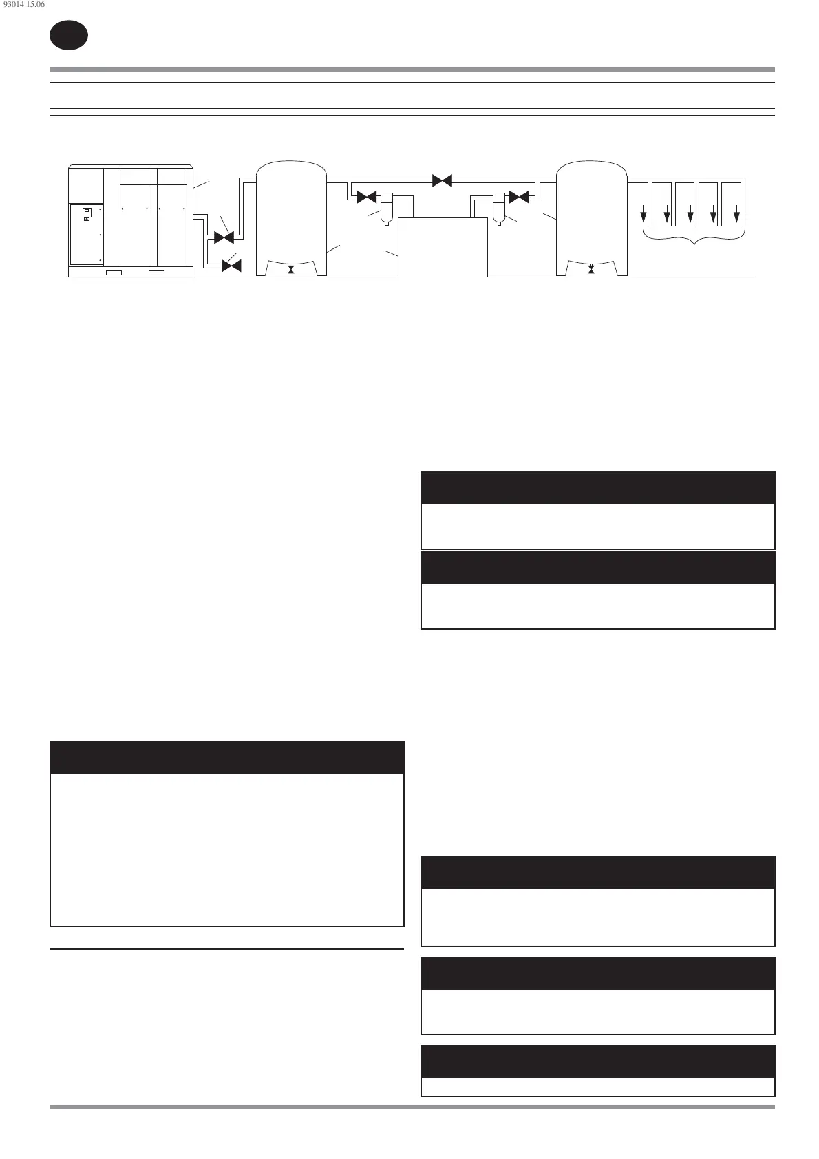
Figure 1 : Typical Air System
2
4
5
4
3
8
6
7
1
Key
Compressor
Air Receiver Dry Tank
Air Dryer
Compressed Air Filters
System Demand Points
Vent/Drain Trap
Isolation Valve
Air Receiver (“Wet Tank”)
Customer can install exible element between machine and pressure
system to avoid vibration transmition.
The compressor can be installed on any level oor capable of supporting
it. A dry, well ventilated area where the atmosphere is as clean as possible
is recommended.
The area selected for the location of the compressor should be free of
dust, chemicals, metal lings, paint fumes and overspray.
Hard surfaces may re ect noise with an apparent increase in the decibel level.
When sound transmission is important, a sheet of rubber or cork can be installed
beneath the compressor to reduce noise. Flexible piping may be required.
See the general arrangement drawing for minimum space requirements
for normal operation and maintenance.
Minimum space in front of the control panel door as required by national
or local codes shall be maintained.
Ambient temperatures higher than 46 °C (115 °F) shall be avoided, as well
as areas of high humidity.
NOTICE
A minimum of 1 m (3.3 ft) all around the compressor is recommended.
If headroom is restricted, then the exhaust should be ducted or
de ected away from the compressor.
Screw type compressors should not be installed in air systems with
reciprocating compressors without means of isolation such as a common
receiver tank. It is recommended that both types of compressor be
piped to a common receiver tank using individual air lines.
The compressor is shipped with the shipping restraints in place.
Ensure that these are removed to allow free movement of the drive
assembly during operation. Each restraint is painted yellow.
Discharge and Condensate Piping
See Figure 1.
It is essential when installing a new compressor (1) to review the total air
system. This is to ensure a safe and e ective total system.
One item which should be considered is liquid carryover. Installation of air
dryers (3) is always good practice since, when properly selected and installed,
they can reduce any liquid carryover to zero.
An air receiver tank (2) is recommended to ensure that the total system
volume is su cient.
1.
2.
3.
4.
5.
6.
7.
8.
•
•
•
•
•
•
•
Discharge piping should be at least as large as the discharge connection
of the compressor. All piping and ttings should be suitably rated for the
discharge pressure. Discharge piping should not exert any unresolved
moments or force on the compressor.
It is good practice to install line lters (4).
Include a vent or drain trap (6) to vent the discharge pipework downstream
from the minimum pressure check valve located on the separator tank and
upstream of the rst system isolation valve (7).
This compressor has an internal discharge check valve. An external check
valve is not required. An isolation valve (7) is required within 1 m (36 in) of the
compressor discharge.
NOTICE
There should be no plastic or PVC piping attached to this compressor
or used for any lines down stream with exception of condensate
removal lines.
NOTICE
The discharged air contains a very small percentage of compressor
coolant and care should be taken to ensure that downstream
equipment is compatible.
When two rotary compressors are operated in parallel, provide an isolation
vaIve (7) and drain trap (6) for each compressor before the common receiver.
Ensure the discharge piping is arranged to prevent water from being forced
into the non-operating compressor.
A wet tank (8) is recommended in cases where the air dryer is a regenerative
desiccant type to prevent short cycling the compressor during the purging
cycle when plant air demand is slow.
The built-in after-cooler reduces the discharge air temperature below the
dew point (for most ambient conditions). Therefore, considerable water vapor
is condensed. To remove this condensation, each compressor with a built-in
after-cooler is furnished with a combination condensate separator/trap.
A dripleg assembly and isolation valve should be mounted near the
compressor discharge. A drain line should be connected to the condensate
drain in the base.
NOTICE
The drain line shall slope downward from the base to work properly.
For ease of inspection of the automatic drain trap operation, the drain
piping should include an open funnel. The drain line must have a
minimum inside diameter of 8 mm (5/16 in)
NOTICE
For low volume systems that may not include an air receiver tank (2),
compressor response time may need adjusting. Contact your local
Ingersoll Rand service provider.
NOTICE
Do not use the compressor to support the discharge pipe.
93014.15.06
 Loading...