ELECTRICAL
4181384 First Edition 4-55
4
Raise/Lower Circuit
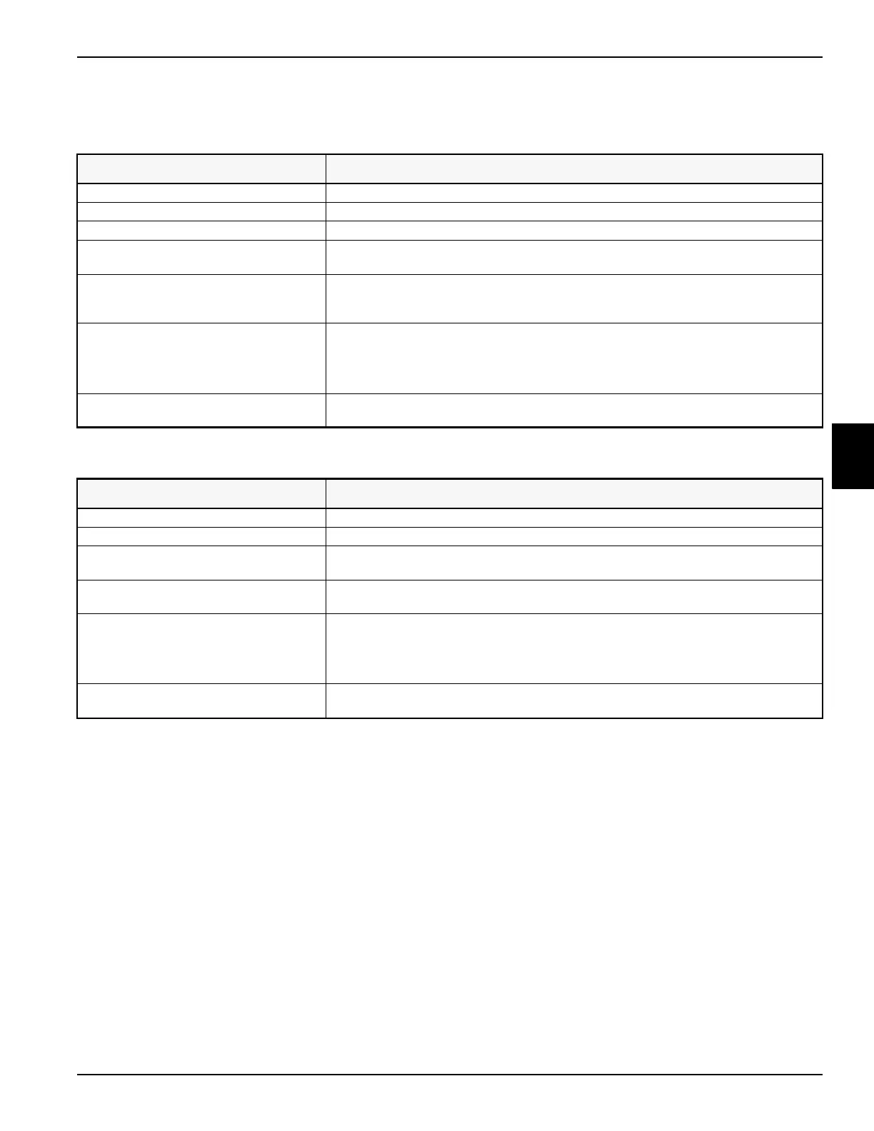
Symptom: Lower solenoid does not energize.
Symptom: Raise solenoid does not energize.
Probable Cause Remedy
Faulty raise/lower switch. Test switch. (See “Joystick Test” on page 4-64.)
Faulty weight transfer switch Test switch. (See “Rocker Switch Test” on page 4-66.)
Faulty lower solenoid. Test solenoid. (See “Solenoid Test” on page 4-68.)
Faulty raise/lower switch 5V power supply
circuit.
Measure voltage between raise/lower switch terminal 4 and ground. Voltage must be
approximately 5 VDC.
Faulty 5V lower switch input circuit. With the raise/lower switch in the lower position, measure voltage between control
module 5V lower switch input terminal and ground. Voltage must be approximately 5
VDC.
Faulty 12V lower solenoid output circuit. Momentarily place the raise/lower switch in the lower position.
Measure voltage between control module 12V lower solenoid output terminal and ground.
Measure voltage between lower solenoid yel/red wire terminal and ground.
Voltage must be approximately 12 VDC.
Open lower solenoid ground circuit. Check continuity between lower solenoid blk wire terminal and ground. Continuity must
be indicated.
Probable Cause Remedy
Faulty raise/lower Switch. Test switch. (See “Joystick Test” on page 4-64.)
Faulty raise solenoid. Test solenoid. (See “Solenoid Test” on page 4-68.)
Faulty raise/lower switch 5V power supply
circuit.
Measure voltage between raise/lower switch terminal 1 and ground. Voltage must be
approximately 5 VDC.
Faulty 5V raise switch input circuit. With the raise/lower switch in the raise position, measure voltage between control module
5V raise switch input terminal and ground. Voltage must be approximately 5 VDC.
Faulty 12V raise solenoid output circuit. Place the raise/lower switch in the raise position.
Measure voltage between control module 12V raise solenoid output terminal and ground.
Measure voltage between raise solenoid grn/wht terminal and ground.
Voltage must be approximately 12 VDC.
Open raise solenoid ground circuit. Check continuity between raise solenoid blk wire terminal and ground. Continuity must be
indicated.
 Loading...