6-50 4181384 First Edition
HYDRAULICS
6
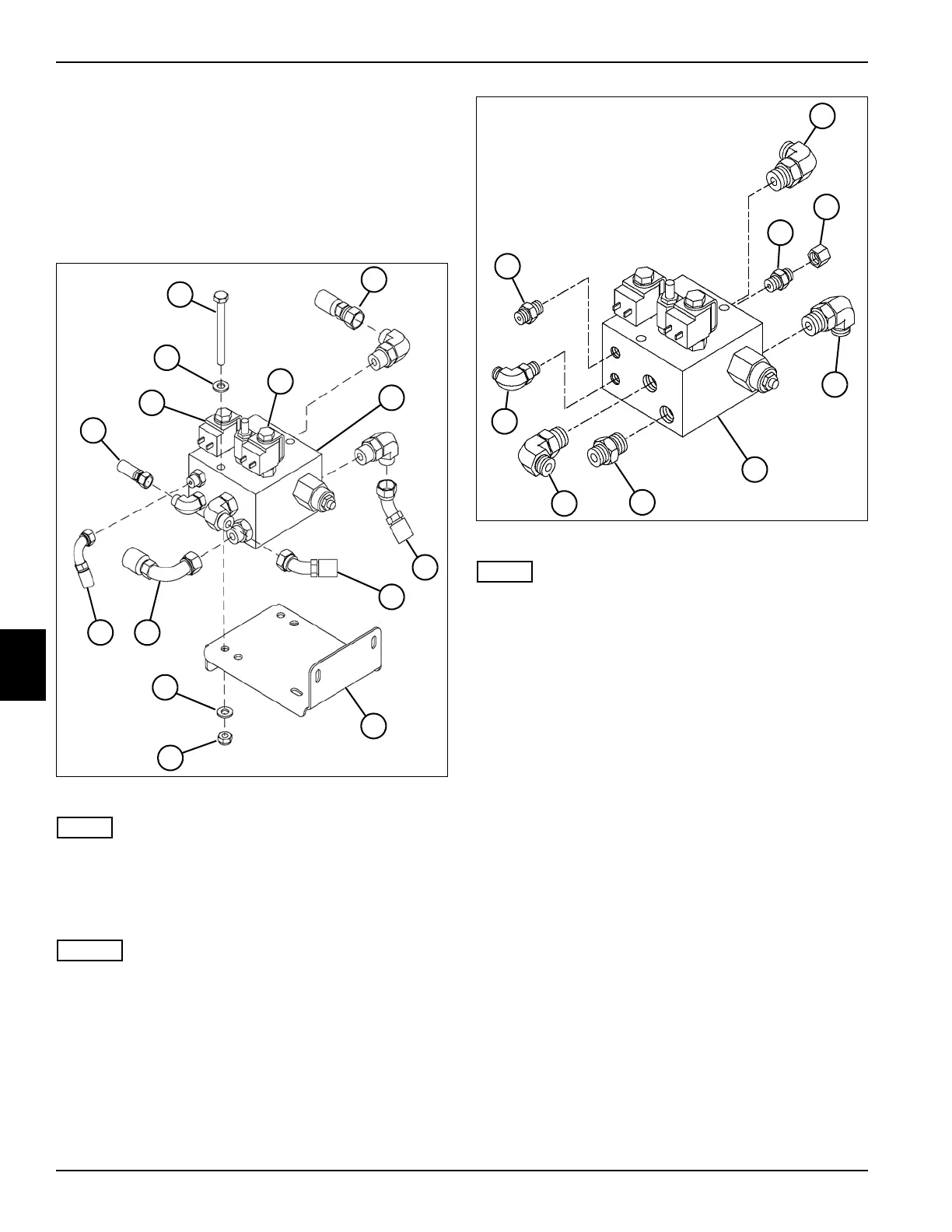
Mow/Brake Valve
Removal and Installation
See Figures 6-45 and 6-46.
1. Park the mower safely. (See “Park Mower Safely” on
page 1-7.)
2. Drain hydraulic oil.
Figure 6-45
NOTE
Label all connectors before disconnecting to ensure
correct installation.
3. Disconnect electrical connectors from solenoids
(2 and 13).
NOTES
• Label all hydraulic hoses before disconnecting to
ensure correct installation.
• Close all openings with caps or plugs to prevent
contamination.
4. Disconnect six hydraulic hoses (3, 5, 6, 10, 11, and
12) from mow/brake valve assembly (3).
5. Remove two nuts (8), screws (1), and four fat
washers (9), and remove mow/brake valve (3) from
bracket (7).
Figure 6-46
NOTE
Record the location and orientation of fittings on lift valve
to ensure correct installation.
6. Remove fitting (14) from mow/brake valve (19).
7. Remove elbow fittings (15, 18, and 21) from
mow/brake valve (19).
8. Remove fitting (16) and cap (17) from mow/brake
valve (19).
9. Remove fitting (20) from mow/brake valve (19).
10. Remove elbow fitting (22) from mow/brake valve (19).
Installation Notes
• Install mow/brake valve by reversing the order of
removal.
• Ensure new O-rings are in place before installing
hoses on fittings.
• Replace hydraulic filter.
• Refill hydraulic tank. (Refer to “Safety, Operation, and
Maintenance Manual” for oil specifications.)
• Start engine and check mow/brake valve operation.
Check for leaks and repair as necessary.
TN1235
13
1
8
2
9
9
3
12
7
6
5
11 10
4
TN1337
15
17
14
18
16
19
20
21
22
 Loading...