ELECTRICAL
4181384 First Edition 4-89
4
Fuel Level Sender
Removal and Installation
The fuel level sender removal and installation is included
in the fuel tank disassembly and assembly procedure.
(See “Fuel Tank” on page 9-6.)
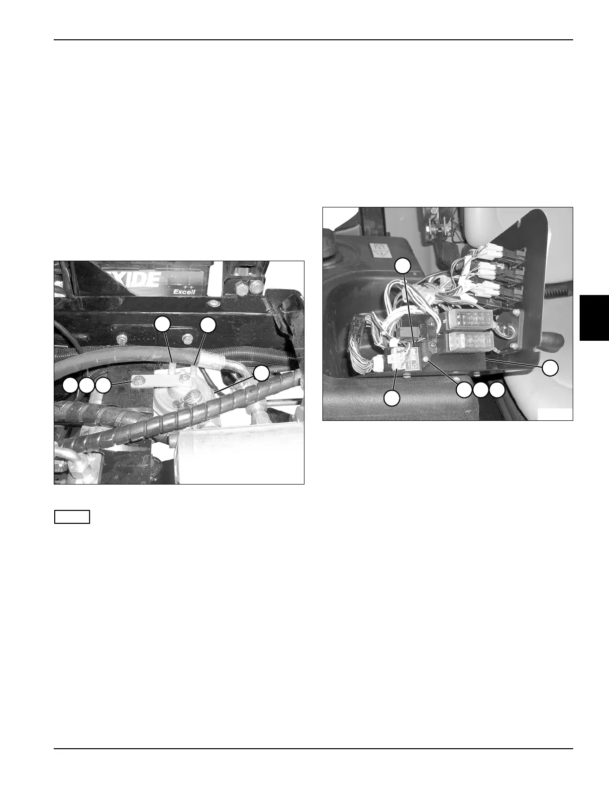
Alarm
Removal and Installation
See Figure 4-90.
1. Park the mower safely. (See “Park Mower Safely” on
page 1-7.)
2. Raise and support the seat platform.
Figure 4-90
NOTE
Label all wires before disconnecting to ensure correct
installation.
3. Disconnect wires (1 and 2) from alarm (3).
4. Remove lock nut (4), screw (5), and two flat washers
(6), and remove the alarm (3).
Installation Note
Install the alarm by reversing the order of removal.
Glow Plug Timer
Removal and Installation
See Figure 4-91.
1. Park the mower safely. (See “Park Mower Safely” on
page 1-7.)
2. Disconnect the battery negative (–) cables at the
battery.
3. Remove instrument panel. (See “Instrument Panel”
on page 4-76.)
Figure 4-91
4. Disconnect wiring connector (6) from the glow plug
timer (1).
5. Remove lock nut (3), flat washer (4), and screw (5),
and remove the glow plug timer (1) from the fuse
block bracket (2).
Installation Note
Install the glow plug timer by reversing the order of
removal.
1
TN1155
2
3
4
5
6
TN1127
3
1
4
5
6
2
 Loading...